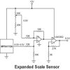
Hi, I am very inexperienced with electronics and need some help working out the components I need. I am measuring temperature with an LM335 and an Atmega16. The Atmega16 has differential inputs on it's ADC but I want more accuracy and have been told I need a differential amplifier.
I want to convert voltage in the range 2.4815-3.4815V into 0.0-5.0V. Please correct me if I am wrong. I think if I make a 2.4815V reference for the (-)input and connect the LM335 to the (+) input and have a gain of 5x I should get the correct output. But I have no idea what component to use for the differential amplifier. I have been looking through parts lists on Digi-Key and other sites and am lost in all the specs of them.
I want to convert voltage in the range 2.4815-3.4815V into 0.0-5.0V. Please correct me if I am wrong. I think if I make a 2.4815V reference for the (-)input and connect the LM335 to the (+) input and have a gain of 5x I should get the correct output. But I have no idea what component to use for the differential amplifier. I have been looking through parts lists on Digi-Key and other sites and am lost in all the specs of them.
")

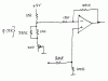
 hm:" according to the attached data sheet. So if I'm not mistaken, at a couple volts the input currents will be so close to nothing that it does not matter.