Continue to Site

Welcome to our site!

Electro Tech is an online community (with over 170,000 members) who enjoy talking about and building electronic circuits, projects and gadgets. To participate you need to register. Registration is free. Click here to register now.

  • Welcome to our site! Electro Tech is an online community (with over 170,000 members) who enjoy talking about and building electronic circuits, projects and gadgets. To participate you need to register. Registration is free. Click here to register now.

Designing LED circuit

Status
Not open for further replies.
The 2N5551 transistors you have are weak. They perform poorly above 50mA.
Ordinary 5mm LEDs light brightly with 25mA and burn out over 30mA.

You want the transistor to fully turn on with a voltage loss of only 0.2V so the 12V supply is reduced to 11.8V for the LEDs.
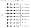
You can use three white or blue 3V LEDs series then their total is 9V. The series current-limiting resistor has 11.8V - 9V= 2.8V across it and Ohm's Law calculates the resistor value to be 2.8V/25mA= 112 ohms which is not a standard value so use 120 ohms.

BUT audio is AC and the transistor turns on for only half of it so the average current in the LEDs will be half and they will look dimmed. Then reduce the value of the resistor to 56 ohms so that the peak current is 50mA and the average current is 25mA.

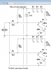
The weak transistor will not be able to drive more LEDs so another transistor and resistors must be used to drive 3 more LEDs.
The series base resistor must have a current of 5mA but we cannot calculate its value without knowing the output voltage of your amplifier.
 
I understand that I will need a number of transistor/resistor/LED circuits in parallel; I had previously figured out that at least for the LEDs, I could have 3 in series before putting them in parallel.

If you excuse the lack of diagramming skill, does this setup look correct, and will the transistor being used as a diode be okay, or will I need to somehow use multiple there as well? newcircuit.png

p.s. Is there anyway for me to test the output of my amplifier? My analog tester thing has settings for 500, 50, and 10v AC, but I think it probably only works at 50/60Hz or something, because I was unable to get a reading from the amplifier when playing music.
 

Attachments

  • Screenshot from 2013-09-03 17:49:26.png
    Screenshot from 2013-09-03 17:49:26.png
    19.4 KB · Views: 148
You have the bases-emitters of all the transistors in parallel which is bad because the transistors probably will not have the same sensitivity unless you are very lucky. The sensitive transistors will light their LEDs but the less sensitive transistors will not. Each transistor needs its own series base resistor for them all to work. Then the transistor used as a diode will be messed up. Use a transistor as a diode for each driver transistor connected at its base.

I do not like your R10 because it might cause all the LEDs to light all the time or cause them to light when the transistors are warm. Try it to see.

An analog meter reads a continuous 50Hz or 60Hz sine-wave, not music that has many frequencies and many levels. An oscilloscope will show the maximum level of music from an amplifier.
 
The sensitive transistors will light their LEDs but the less sensitive transistors will not. Each transistor needs its own series base resistor for them all to work. Then the transistor used as a diode will be messed up. Use a transistor as a diode for each driver transistor connected at its base.
How would I go about setting that up?

I do not like your R10 because it might cause all the LEDs to light all the time or cause them to light when the transistors are warm. Try it to see.

Alec suggested R10, as long as I keep the resistance high enough to not turn on the transistors by itself. I will make sure to experiment to find a high enough value.
 
That makes a lot of sense.

To be clear, I will have to experiment for the R2 value in your diagram, but will R1 be dependent on the music? How should I determine its value?
 
The value of R1 depends on the output level from your amplifier:
1) 10W into 8 ohms is 12.9V peak so R1 should be (12.9V - 0.7V)/5mA= 2.4k ohms.
2) 100W into 8 ohms is 40V peak so R1 should be (40V - 0.7V)/5mA= about 8.2k ohms.
 
Thanks for all the help so far! Once I get to building it, I will make sure to keep you updated. Especially if there are problems ;)
 
Last edited:
After doing various tests using white LEDs, and preparing the actual speakers, I realised that I forgot something. I started designing the actual layout of the circuits for soldering, however I am going to be using common cathode RGB LEDs31PvQvZBwCL.jpg. The circuit design currently has the resistor plus transistors on the ground, so if they changed, it would affect more than one color. Is there a way to properly move the series resistor to a place where it won't affect multiple colors on a single LED?
Thanks
 

Attachments

  • LED circuit.png
    LED circuit.png
    30.6 KB · Views: 143
Common-cathode LEDs are driven with PNP transistors but your transistors are NPN.
 
The LEDs in your circuit are shown as series-connected, not common cathode ??
 
Sorry if I wasn't clear. My setup will have probably 24 RGB LEDs. They will be in sets of 3 because of the 12v power supply. My issue is attaching multiple colors to the power but giving them different current limiting resistors. So, originally I had thought I would use the setup (I copied it into my last post) where two of the circuits are basically in parallel, to use the same power and music source (so on that diagram, the two parallel circuits would be, say, red and blue on the same LED). I hadn't noticed at the time that I wouldn't be able to use a common ground for them.

AG, I understand that I hadn't adequately prepared for this project, however is there any way to modify the current setup without having to get PNP transistors?
 
Common-cathode LEDs cannot be connected in series and cannot be driven by NPN transistors unless all 3 colors are driven at the same time.

Each common-cathode RGB LED needs three current limiting resistors in series with each color and three PNP driver transistors if the colors are turned on separately. With a supply as high as 12V then the current limiting resistors will get hot and maybe level-shifting must be done so a 5V supply should be used.
 
Last edited:
Since the power supply is from a computer, I can use 12 or 5 v.

To make sure I am understanding: even with the correct transistors, I will not be able to run multiple RGB LEDs in series (e.g. 3 blues together, 3 reds together, and 3 greens together)?

Would these transistors work for this situation: https://www.amazon.com/Amico-Termin.../ref=lh_ni_t?ie=UTF8&psc=1&smid=AXQTV6S8EDR15

I prefer to get the correct parts this time :/

Thanks
 
You cannot connect common-cathode or common-anode LEDs in series. For your LEDs, each color needs its own series resistor. With a supply as high as 12V then the resistors will get hot and a level-shifting circuit is probably needed so use a 5V supply.

Your NPN transistors can be used as emitter-followers to drive your common-cathode LEDs if your signal source allows it. What is the signal source?

A 2N3906 PNP transistor can drive one color at 20mA. Each transistor needs a series base resistor. But whatever you have that drives the transistors might be overloaded when trying to drive 72 transistors.
 
My signal is the output from an audio receiver. Although I don't know its peak power output, based on the speakers' SPL ratings and how loud I use them, it will generally be around 1-3 Watts. What types of sources can and cannot use NPNs as emitter-followers, what decides it?

If the audio source does allows it, would I make my circuits emitter-follower by moving the load to the emitter side of the transistors (obviously flipping the LEDs)?

The PSU I am using is rated at a total of 270W, with the 5V rail at 22A, so around 110W max. I think that would be more than enough for the LEDs.

EDIT: On another thread, MrAl said
The individual RGB LED's can not be paralleled at all because only the red LED would light up, or the green and blue would be very dim that way.
Does that apply to my situation?
 
Last edited:
Why RGB? Are you intending to have R for one signal strength/frequency range, G and B for other ranges?
 
I will be connecting the signal sources to the LEDs after the speaker's internal crossover. R will be for higher frequencies, and B for lower frequencies (probably with a larger resistor to balance R). I probably won't use G because the speakers only have 2 cones.

So yes, my plan was for the color to correspond to the general frequency.
 
1W into 8 ohms is 2.83V RMS which is 8V peak-to-peak. The positive peak of +4.0V will drive the bases of NPN emitter-followers and the emitters will go as high as +3.3V which might not be high enough to light blue LEDs and is certainly not high enough for some voltage across the current-limiting resistors.
Since sound has a wide range of levels then some sounds will have enough amplitude to barely light blue LEDs and most other sounds will not light blue LEDs.
There is not enough voltage available when emitter-followers are used with the very low speaker levels.

If the signal level into the base of the emitter-follower exceeds the 5V supply by 0.7V (which will probably happen) then the transistor will be destroyed unless a current-limiting resistor is added.

A Color Organ circuit uses a sensitive amplifier driving the LEDs. Then almost ANY sound level at the correct range of frequencies light the LEDs.
 
I don't think I properly understand what the emitter-follower circuit would be doing. Aren't the transistors supposed to be increasing the output so the smaller input signal is amplified to be able to drive the LEDs? From what you are saying, they don't amplify at all.
 
Status
Not open for further replies.

Latest threads

New Articles From Microcontroller Tips

Back
Top