Continue to Site

Welcome to our site!

Electro Tech is an online community (with over 170,000 members) who enjoy talking about and building electronic circuits, projects and gadgets. To participate you need to register. Registration is free. Click here to register now.

  • Welcome to our site! Electro Tech is an online community (with over 170,000 members) who enjoy talking about and building electronic circuits, projects and gadgets. To participate you need to register. Registration is free. Click here to register now.

Designing LED circuit

Status
Not open for further replies.
First of all, most of my electrical knowledge (and there isn't much of that!) to date has been self-taught from the Internet, so please bear with me.

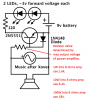
I am attempting to create a circuit using the audio from a receiver to pulse LEDs. Eventually, it will be using RGB LEDs, with red on high frequencies and blue on low, and an old spare computer PSU (which has 12v, 5v, and 3.3v outputs) to power it all. For now, my testing setup is 2 white LEDs plus a 200 ohm resistor attached to a 9v battery and a transistor to the music (see attached schematic).
This current test works (the LEDs pulse with the music), however I have to turn the volume up uncomfortably loud for the low frequency LEDs to start blinking, and even louder for the high frequency ones to do so. I understand why it needs more power before the HF ones work, however I would like them to light at more normal volumes, and equalise the low and highs in terms of LED light.

When I first planned this project, I assumed the transistor+extra power would be enough, and maybe just use larger resistors for the low end than high, however now it seems like I will need to do more. I have read a bunch about Darlington pairs, however I don't seem to grasp how to efficiently make them work (since they have a doubled initial voltage?) without wasting a lot of power or burning out my transistors.

In case this is necessary for any help, what I have:
-Standard resistors, 10 Ohm-1M Ohm (31 values, a total of 775 resistors)
-A bunch of 200 Ohm resistors that came with my LEDs
-100 White LEDs, I am using for testing and probably some for the actual design later
-50 RGB LEDs, I will be using for the actual result
-100 2N5551 transistors (well, I killed one) with these specs, according to Amazon where I got them: Collector Base Voltage: 180V; Collector Emitter Voltage: 160V; Emitter Base Voltage: 6V; Collector Current(Continuous): 600mA; Collector Power Dissipation :0.625W
-Soldering iron, solder, various insulated wires of different gauges, etc.
-Whatever random household materials are around

Again, I don't know much about how current, voltage, resistance, etc. will affect things, and I have mostly been using online calculators, so any help would be greatly appreciated!
 

Attachments

  • Circuits.png
    Circuits.png
    103.7 KB · Views: 234
Last edited:
The extremely simple circuit is missing some important details.

Your transistors are connected as "emitter-followers" that have no voltage gain, actually they have some voltage loss. Then they must be driven from the output of a power amp, not from a music source. The two 3V LEDs in series with 200 ohms will light brightly with an output from a transistor of +10V peak and the output from the amplifier must be +10.7V peak.

When the peak signal voltage +10.7V then the power into an 8 ohm speaker is 7.2W RMS.
When the amplifier signal reaches 7.2W then the LED will blink but the signal also swings to -10.7V peak which will damage the transistor that has a max allowed Veb of only 6V. The transistor will break down which might also destroy the power amplifier.

If the circuit is driven from the output of a power amplifier then the transistor and battery are not needed and can be replaced by a diode so that the max negative allowed voltage on the LEDs ((usually 5V each) is not exceeded. The value of the 200 ohm resistor must be calculated with the maximum output voltage from the amplifier.

A more complicated circuit will blink the LEDs much better and might have automatic level control.

Was this horrible circuit an "Instructable" that have many errors like this?
 
You caught me :p, this was based on this www.instructables.com/id/Stereo-Speakers-with-Synched-LED-Lighting/?ALLSTEPS instructable. Obviously I have misunderstood what I did learn about electronics online.

Since it is apparent that I don't have much experience in voltage/amperage stuff, is there any way that I can make a working model, even if it is more complicated, with the materials I pointed out above? I don't have any diodes, unless the LEDs count. I definitely don't want to destroy my amplifier or any more transistors!
Thanks for responding, I have already learnt more by your post :rolleyes:
 
Last edited:
If you want a circuit to distinguish between low, medium and high frequencies you will also have to buy some capacitors.
Google for 'color organ schematic' and you will see capacitors being used for frequency filtering.
 
The designer of the Instructable says it is his first one. Maybe he is only 10 years old like many designers of Instructables who know NOTHING about electronics.
I saw no schematic so I do not know how the parts are wrongly connected.

You do not need to make the LED circuit distinguish the frequencies because the crossover network does that. The woofer plays low frequencies and the tweeter plays high frequencies.
 
Alec,
As Audioguru says I already have it set up as one circuit for low frequencies, one for highs, using the components of the speaker.

Right now, I just need to figure out how to boost the output to the LEDs properly, which apparently just means changing my circuit. Audioguru, the schematic in my first post is exactly how my stuff is currently connected, so I think we can safely ignore that Instructables from now on. If I can change my circuits (low and high) to each be set up in a way that makes more sense for amplifying the voltage (voltage my issue with the LEDs, right?), that would be great!
 
I fixed the horrible very simple circuit so that it has voltage gain and has a base resistor and diode to prevent the amplifier and transistor from blowing up.
The base resistor value must be calculated so that it turns on the transistor properly but that it does not get too hot and blow up the transistor at the max output voltage of the amplifier.

There is no control of the level that turns on the LEDs so the amp volume control is the only level control.
An LED level control can be added to feed the base resistor.
 

Attachments

  • LED circuit.png
    LED circuit.png
    67.4 KB · Views: 169
This is like AG's circuit, but uses Q2 configured as a diode (since you don't have any) :-
Sound2Light.gif
 
Thanks so much for the diagrams! Alec, could you possibly explain how your diagram works? I don't exactly understand what Q2 is doing when placed like that.
 
Last edited:
Q2 in Alec's schematic is used as a diode to conduct and protect the emitter-base of Q1 from exceeding its max allowed reverse voltage of 5V or 6V.
 
Thanks again! After I test this, I just need to adapt it to a PSU, and with more LEDs...
 
The new design works fine, however it still needs the volume cranked up pretty high before the LEDs light up. I don't need a fancy control deciding how loud I want it before they light up, but is there any way to increase the amplification in this circuit?
 
You could try reducing the 1k resistor to 330Ω (I wouldn't go lower or you risk passing excess current through the base of Q1).

Edit:
is there any way to increase the amplification
If only you had a capacitor........ Can you rescue one or two from some dead electronic gizmo?
 
Last edited:
Reducing the resistor value helped the low frequencies, but isn't nearly enough for the high frequencies.
I definitely could find some random capacitors around from stuff, but not of any specific value. How would those fit into the circuit, and what would they do?
 
The new design works fine, however it still needs the volume cranked up pretty high before the LEDs light up. I don't need a fancy control deciding how loud I want it before they light up, but is there any way to increase the amplification in this circuit?
A proper LED circuit uses an opamp that can provide any amount of amplification. The transistor in your extremely simple circuit needs an input of at least 0.7V to turn on the LEDs.

You never told us what is the input so I just guessed that it is from a power amplifier with plenty of output voltage. Maybe your input is a tiny signal from an MP3 player?
If you connected the pins on the transistor wrong then the LEDs will barely light up.
 
With the limited choice of components you have, here's another way of improving the sensitivity slightly (but as AG points out you really need an opamp to get more amplification):-
Sound2Light2.gif
You may have to experiment with the value of R2. Something between 10k and 15k should do if R1 = 1k. R2,R1 help the transistor to turn partly on in the absence of audio. A smaller audio signal than 0.7V can then turn the transistor on fully.
 
The signal is indeed from a reciever/amplifier, powering two loudspeakers (old Technics SB-L35 speakers, if you want to know). My LEDs are then in parallel with the woofer and tweeter. I assumed this would be enough power to activate the transistors. I have checked and rechecked the transistor pins, I don't think that is an issue.
That makes a lot of sense, alec! One question to make sure I don't ruin it: The crossing of wires in the middle of the diagram, not touching correct?
 
Not touching. (Wire joins are marked with a blob; cross-overs aren't).
 
I have some powered speakers that are rated at 150W or 75W. Their actual maximum output is about only 2W or 4W per channel.
They will drive the circuit I posted VERY well. Maybe the output from your receiver/amplifier is almost nothing?

I hope your LEDs are NOT parallel with a speaker. They should be driven by the transistor.
 
My speakers are rated for 100W, but I don't know what the receiver usually outputs, I don't have a multimeter right now, only a bad analog battery tester thing.
Sorry for the confusion, I didn't mean they were parallel. The circuit is set up like you guys suggested, using the transistor.
When I build my actual design with the computer PSU (probably the 12v rail) and a lot more than 2 LEDs, which resistors will have to be adjusted? Besides the simple one in series with the LEDs, how do I calculate them?
 
Last edited:
Status
Not open for further replies.

Latest threads

New Articles From Microcontroller Tips

Back
Top