Continue to Site

Welcome to our site!

Electro Tech is an online community (with over 170,000 members) who enjoy talking about and building electronic circuits, projects and gadgets. To participate you need to register. Registration is free. Click here to register now.

  • Welcome to our site! Electro Tech is an online community (with over 170,000 members) who enjoy talking about and building electronic circuits, projects and gadgets. To participate you need to register. Registration is free. Click here to register now.

Designing a Analog to Digital Converter

Status
Not open for further replies.
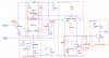
Do you have plenty of power supply decoupling caps, and good ground planes? You should have, at minimum, a 100nF cap from each supply pin to GND on each IC (or circuit, when you go discrete). The fact that you get different answers with and without the AND gate implies to me that you need better decoupling and/or a pullup on your AND gate output (or a CMOS AND gate). Re-read my comments about logic levels.
Your LSB is only 20mV. Digital noise can easily be 10 times this. It is best to have separate analog and digital ground planes, with them connected to each other at one point only. I don't think this will work in the case where you are using the SAR outputs as the switches for the ladder network.
Since you are also using +5V for analog and digital purposes, you need to be sure that +5V is extremely clean (well-filtered/decoupled). It is the reference for your A/D and for your D/A.
From a noise standpoint, it would be better to have a separate analog +5V, with a D/A which does not use the outputs of the SAR as the switches for the ladder network, because the SAR puts a lot of undesirable current transients on the +5V supply.
 
Hey Roff i got around to building the circuit and something isnt working right. Input transistor one gets very warm and regardless of the input state the output is 5 volts ?
Any ideas where i can look to fix the problem ?

Thanks
pete
 
What type of transistors did you use? Did you make any assumptions about the pinouts on them?
 
You wont believe the stupid mistake i made ....lol
I assumed that the transistors are the common EBC pin variety so when i connected it all together nothing worked. Yesterday night it hit me to check everything and look at the data sheets and then i realized they aren't the normal pinout but rather BEC. I will try that today..

Can u please explain the purpose of the diodes ? Also in brief the purpose of the different stages...I recognize the first stage as being a diff amp...

Thanks
pete
 
amdkicksass said:
You wont believe the stupid mistake i made ....lol
I believe it. That's why I asked the question. Don't feel like the Lone Ranger.
I assumed that the transistors are the common EBC pin variety so when i connected it all together nothing worked. Yesterday night it hit me to check everything and look at the data sheets and then i realized they aren't the normal pinout but rather BEC. I will try that today..

Can u please explain the purpose of the diodes ? Also in brief the purpose of the different stages...I recognize the first stage as being a diff amp...

Thanks
pete
D1 and D2 keep Q1 and Q2 out of saturation (saturation takes time to recover from). They also limit the signal swing into the second diff amp, allow it to fully switch (with large-signal inputs), but minimizing the overdrive recovery time that would be required if they were absent. They add unwanted capacitance, so small-signal Schottkys (with low capacitance) were specified. D3 keeps Q10 out of saturation, and also limits the overdrive recovery time at the base of Q11, by clamping the swing to +0.7/-0.4V.
Overdrive recovery time is a function of the current available to charge and discharge the capacitance of a node, and the voltage over which that node must move before switching occurs.
EDIT: Below is an annotated schematic.
 

Attachments

  • comparator annotated.PNG
    comparator annotated.PNG
    42 KB · Views: 239
Last edited:
Status
Not open for further replies.

Latest threads

New Articles From Microcontroller Tips

Back
Top