saiello
New Member
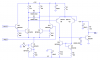
I tried using the LM311 in one of my circuits and although supposedly a simple device in theory, as a newbie to electronics I had some problems getting it to work properly. Here are some pointers.. .The LM311 will work with a single +5V supply ( Pin 8 ) and 0V ( Pins 1 and 4 ). Pins 5 and 6 should be shorted together. The inputs ( Pins 2 and 3 ) can range from 0v-5V ( i.e. rail-to-rail ) without adversely affecting the 311, BUT you must ensure that at least one of the inputs is at, or below 3.5V or switching won't occur! ( another head scratcher, 'til I found out about common mode voltages!  ). Adding a bit of hysteresis wouldn't go amiss either and will help eliminate output oscillations around the switching threshold, but again watch that the varying switching threshold due to the added hysteresis doesn't wander above that 3.5V upper limit..!
). Adding a bit of hysteresis wouldn't go amiss either and will help eliminate output oscillations around the switching threshold, but again watch that the varying switching threshold due to the added hysteresis doesn't wander above that 3.5V upper limit..!