Continue to Site

Welcome to our site!

Electro Tech is an online community (with over 170,000 members) who enjoy talking about and building electronic circuits, projects and gadgets. To participate you need to register. Registration is free. Click here to register now.

  • Welcome to our site! Electro Tech is an online community (with over 170,000 members) who enjoy talking about and building electronic circuits, projects and gadgets. To participate you need to register. Registration is free. Click here to register now.

Design Help Needed

Status
Not open for further replies.
shermaine said:
hi guys,

i make a mistake. The voltage is same for pin 9 of u2a and pin 8 of u1c. they are 4.4v. As for pin 8 of u2a , it is 0.1v. Guys, is there any thing wrong with the dip switch connection? Please advise. Thanks.i'm making use of pin and pin4 only. is that correct?
It does not matter which switches you use for S0 and S2. 1 & 4 is OK.

Just check that D0 goes from High to Low when S0 is closed and that D2 goes from High to Low when S2 is closed.

Is the oscillator working????

I suggest you measure all of the voltages and post the circuit again with them marked on it.
 
here's the measured voltage.
 

Attachments

  • voltage meaured.JPG
    voltage meaured.JPG
    224.8 KB · Views: 217
when i on pin 1 of dip switch, it is red light.
when pin 1 and pin 4 of dip switch on , it is green light.
when pin 4 of dip switch on, it is green light.
when all off pin 1 to pin 4, it is red light.
 
shermaine,
Looking at your last drawing, you are showing pin 3 on the 555 as +4.9v.

If the 555 timer is running at 1Hz, then this voltage should be going high and low!, NOT steady at 4.9V.

Where are the components for the 555 timer ?, not shown on drawing.
 
shermaine said:
here's the measured voltage.
There are some inconsistencies in the measurements.

U1/6 is shown as 4.35V but U5/11 and U4/3 are shown as 0.19V. These should all be 4.35V given that U1/5 is at 0.06V.

U3/1 is 1.5V, U3/4 is 7.5V (this must be a mis print) the other points on this line (eg. 555/3 are 4.95V. So there is something wrong here. Is there a bad connection?

As Eric said, the clock should be pulsing high and low.

You could slow the clock down further to say 0.5 Hz so the highs and lows are about 1 second to make it easier to read the voltage as it changes.

You could use the other half of U4 to divide the clock frequency by 2.

To do this, connect the 555/3 to U4/12, connect the clock line (ie. what used to be connected to 555/3) to U4/10. Connect U4/13 to gnd
 
shermaine said:
Hi eric,

the 555 timer is as attached.can u advise. thanks.
The 555 needs 2 resistors and a capacitor to make it work. See page 6 of the attached data sheet.

For 1 Hz use Ra = 68k, Rb = 39k and C = 10 uF.
 

Attachments

  • 555.pdf
    120.2 KB · Views: 180
Hi guys,

Thanks! I got no 68Kohm and 39kohm resistor and capacitor now. So i can't do the testing now. Btw, do u mean there is connection error between U5, U1, U4 and U6 points and the clock? Could the reading be cause by the clock?
 
I'm using ST NE555 IC. It seem to state RA = 51kohm from pin 4 to pin 7 and RB = 22kohm from pin 7 to pin 6 and C = 0.01uf from pin 6 to pin 1. I do have 100kohm resistor and 100n cap. Can i use a higher range? Please advise. Thanks.
 

Attachments

  • ne555.pdf
    492.3 KB · Views: 273
Last edited:
hi,
If you use the values that you have stated, the clock frequency will be to fast, you will not see the LED's flashing.

Get the values that Len has stated.

EDIT:
thanks! but the ic chip i'm using is from st microelectronics and not philips.
can i still use bake the st microelectronics values? please advise. Thanks
.

Yes thats OK, just use Len's components.
 
Last edited:
thanks! but the ic chip i'm using is from st microelectronics and not philips.
can i still use bake the st microelectronics values? please advise. Thanks.
 
shermaine said:
thanks! but the ic chip i'm using is from st microelectronics and not philips.
can i still use bake the st microelectronics values? please advise. Thanks.

hi shermaine, which day do ya hav to submit ur project??
i found this forum juz now.. i m also doing the same project as urs.
but i use the tutor design..
 
Could there be a connection error between U5, U1, U4 and U6 points and the clock? Could the reading be cause by the clock?
 
hi,
If you have connected the Clock lines as Len's drawing I cannot see a problem.

Look at the attached drawing, use the spare gate on U2c [7410] and wire it as the drawing.
Connect a short piece of wire as the Logic Test Probe.

When the circuit is powered ON, touch the Test probe onto pin #3 of the 555,
the LED should flash at about 1 second intervals.[ this will test the clock]

If the LED dosn't flash, disconnect pin3 of the 555 from the circuit and try again,
[ see if it flashes if nothing else is connected] Let us know what you find.


You can use the Test probe to check other parts of your circuit.

When the Test probe is connected to a Logic High the LED will light.
When the Test probe is connected to a Logic Low the LED will NOT light.
 
Last edited:
shermaine said:
Could there be a connection error between U5, U1, U4 and U6 points and the clock? Could the reading be cause by the clock?
I think you mean U3 not U1. The clock line does not go to U1.

Your wiring diagram and my circuit show that 555/3, U5/14, U3/1, U3/4, U6/11, U6/3 & U4/4 are all connected together.

Therefore you should read the same voltage on all of them.

But your voltage measurements show that U3/1 and U3/4 are different to the others. So there must be a bad connection.

Also, your measurements indicate that U1/6 has 4.35 V on it, but U5/11 & U4/3 have 0.19V on them. Again, there must be a bad connection.
 
hi shermaine,

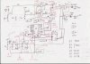
the tutor's design is same with what u hav post on "Enquiry" thread.
the link is

I check the design alrdy..everything is fine.
except AND gate before the green led; tat gate is missing an input (output from JK flipflop).
and also B0 should be connected to ground also.

I edit his design with red color.
pls hav a look.
(note: u don't need to connect any unused output pin.. juz leave it unplugged.)
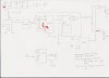
The explanation is

First part is

in the JK chip

The combination inputs (Ripple signal from CountUp + "A" confirm signal) are supposed to give the toggling output for 16 clk-cycle of period.

So we got the toggling signal from JK flip flop.


Second Part is

For the rest of the chips, it is easy to see tat

Since the only tsunami level 4-5 need red light, we consider implementing the period of red light out of 16 clock cycles. After the red period, the green light will be switched on by using an inverter logic gate for the rest cycles out of 16.

The Adder does the multiplying the input tsunami levels by 3. Eg. 1 -> 3, 2->6, 3->9, 4-> 12, 5->15..
U can see tat the 12 and 15 is the number wat we want red LED to be on.

In the Countdown chip (after the adder in blueprint)

The Load pin is set the starting input and the counter will count down to 0000 (which is used as feedback again to disable the chip when it reaches 0000.)

Signals below tsunami level3 are cut down by AND gate.

Finally we get the desired clk-cycle period to switch on red and green LED in desired order.

For Example, Tsunami level 4 input, we get the red light on for 12 clk-cycle period; after tat, green light will b on.

Then by combining the First part Toggling output from JK, we get the blinking red and green light.


Hopefully u will understand easily.
Actually u don't realli need ur circuit working perfectly.
If ur logic is correct, tutor will accept ur circuit design.
My one has flashing problem. but it works properly for desired period except LEDs r not blinking.
But tutor said it is quite ok as long as i can explain the circuit.

Today i finished my presentation. I had to explain the whole circuit to tutor.
U do need to understand the logic since tutor will test u with some questions differing frm our project question.

Good Luck.
Vandor
vandor is online now Forward Message
 

Attachments

  • Tsunami.JPG
    Tsunami.JPG
    128 KB · Views: 160
Status
Not open for further replies.

Latest threads

New Articles From Microcontroller Tips

Back
Top