Electro Tech is an online community (with over 170,000 members) who enjoy talking about and building electronic circuits, projects and gadgets. To participate you need to register. Registration is free. Click here to register now.
Welcome to our site! Electro Tech is an online community (with over 170,000 members) who enjoy talking about and building electronic circuits, projects and gadgets. To participate you need to register. Registration is free. Click here to register now.
The small contacts on the breadboard cannot conduct more than about only 100mA.
Your thin wires also cannot conduct more than 100mA.
But parts of the inverter must conduct 15A!
Get rid of the breadboard and make a pcb with wide traces.
Or wire a circuit with stripboard.
A 100W square-wave inverter takes 120W from the 12V battery so the battery current is 10A.
100W at 120V Needs a battery current of 10A.
Each output transistor must conduct 10A. The base current of each output transistor will be about 3A or more.
The CD4047 oscillator can provide about only 10mA max so you need a current booster to boost 10mA to 10A for each output transistor. The driver transistor and output transistor on each side must do that.
well i happened to stumble on 2n3055 transistors already sitting on some heat sinks. but i just wanted to see whether i could get at least an output before i can think of doing anything. i tried measuring the output on the first set of op amps. it gave me roughly 10 volts like you said but it is not a square wave instead it is just straight dc.
I tried measuring the output on the first set of op amps. It gave me roughly 10 volts like you said but it is not a square wave instead it is just straight dc.
Sorry, I was wrong. The base-emitter Diodes of the driver and output transistors limit the output voltage of the opamps to 1.2V to 2.2V.
since you have 10VDC then the transistors are the wrong ones, or they are connected backwards or they are blown up.
Did you use an LM358 dual opamp?
Do you have square-waves at the outputs of the CD4047 IC?
i have a question about my 1k resistors and my 4.7 k resistors. i am guessing they should be very high power resistors meaning that they are required to be very big since you said that a total of five volts is coming out of them.
got a battery.... got a battery that might deliver the desired output current..... but it ready 12V output but the current reading is 275 - cranking amps and 230 - cold cranking amps... that is all i see.
i have a question about my 1k resistors and my 4.7 k resistors. i am guessing they should be very high power resistors meaning that they are required to be very big since you said that a total of five volts is coming out of them.
No.
1/4W resistors are fine.
The 1k resistors have a max of 1V across them so they dissipate only 1 squared /1000 ohms= 1 milli-watt for half the time. Up to 250 milli-watts is allowed for a 1/4W resistor.
The 4.7k resistors have almost no current so they do not get warm.
You need to fix the problem of the transistors that causes the output voltages of the opamps to be DC at a voltage much higher than normal.
got a battery.... got a battery that might deliver the desired output current..... but it ready 12V output but the current reading is 275 - cranking amps and 230 - cold cranking amps... that is all i see.
It is a car battery that is not good for an inverter. It is designed to deliver up to 275A for a few seconds to start a car's engine. You need a "deep discharge" battery designed for motor homes instead. The car battery is destroyed if it is discharged too much.
yes i figured as much..... i looked around and there was nothing else available. the only thing i got for now ( which i will only use for testing purposes) is a 12 volt battery that delivers 5 amps. will that work or will i need to get two of them since you said that battery needed to deliver 10amps of current. also i didnt make so much progress on trouble shooting the voltage at the op-amp today as it was a really busy one. i will tackle it tomorrow most definately.
A 12V/5Ah battery can supply 12V x 5A= 60 Watts for about 20 minutes. It can supply 3 Watts for 20 hours. The inverter will have a max output power of 50 watts and will heat with 10 Watts.
What will you power with the inverter? Its output is a square-wave that will not power many electronic things.
i am merley going to test it on a light bulb. i i just want to make sure it works, once that is done i can modify the circuit and then build something more robust so that it could be added to an already constructed solar panel.
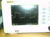
ok/...... i started over circuit construction and this so far is the output from the lm358 op amp at both outputs 1 and 7. it give a square wave but the peak to peak voltage is about 13V. attached is a photo..........
do you have any suggestion for a light load? i just want to show that it works. also what do you think about the output on the op amp and astable vibrator.
the circuit once again is complete but the desired output still cannot be obtained. for some reason, i i basically get the same output 12v approx. across the transformer output. which means in the end there is not boosting on the transformers behalf.
This site uses cookies to help personalise content, tailor your experience and to keep you logged in if you register.
By continuing to use this site, you are consenting to our use of cookies.