Continue to Site

Welcome to our site!

Electro Tech is an online community (with over 170,000 members) who enjoy talking about and building electronic circuits, projects and gadgets. To participate you need to register. Registration is free. Click here to register now.

  • Welcome to our site! Electro Tech is an online community (with over 170,000 members) who enjoy talking about and building electronic circuits, projects and gadgets. To participate you need to register. Registration is free. Click here to register now.

Design an adjustable voltage switch

Status
Not open for further replies.
Ron,

Thanks for spending time on this. I am well aware of ones "spare time"

If you go back to the beginning of this thread, these components were given to me by various people. I think Eric might have been the guy who rec'md the 2N2222.
I will use my own 8V Vreg, or the one posted a page back. (Although not sure why I need an adj one.)
Can you get a 2N5550 to replace the 2N2222?
If you read the text where I posted the regulator, you'll see that I recommended 78L08 or LM317L.:) If you use 78L08, the cap on the input side needs to be 330nF instead of 100nF. 330nF should also work for LM317L.

I think using both sides of the LM393 is just as good. A MOSFET would require adding in another component which takes away board real estate.
The MOSFET would replace the NPN. You would actually save a couple of parts (the 100k divider), but the MOSFET I have in mind is surface mount.

I am going to start over and make all new boards. I will order any new stuff from digikey. So if you feel that other components are worth changing, LMK and I will order those as well.

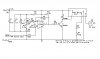
Please verify components:

U1 = POT 1K?
U3 = POT 500K? (adj Hysteresis )
LM393 Vcc = 8V ? ( I assume since you have an "8" below the Vreg symbol.
LMK???
The pot values are correct.
The schematic shows power pins on both LM393 sections. This is so the simulation will run. See the LM393 datasheet for pinout.
The 1k pot sets the low side of the hysteresis range. The range of adjustment is nominally 3.3V to 4.0V. You said you wanted 3.65V. This voltage is independent of the 500k pot setting. It will change when the relay coil is energized, but is not relevant during this time.
The 500k pot does adjust hysteresis, but you might want to think of it as the threshold adjustment. The range is nominally 4.4V to 4.9V, subject to component tolerances.

Lastly, I do not see any Zener's here. Does this new design eliminate them? Since adjusting the Vsrc is so limited for my usage (4.0 to 4.7 range)
The zener is not needed. The 8V regulator is a better reference than the zener.
Lastly, this new circuit above, is it totally complete? I ask because the configuration on R1 and R2 is different than my original that has caps and Zener's to the left.
I believe it's complete except for the aforementioned voltage regulator, which is posted on the previous page. You should also add 100nF caps from LM393 pin 8 to GND, and from the terminal of the relay coil that connects to the battery.

You obviously should not commit to large quantities before you test the design.
 
LMK = Let Me Know~!
2N5550 is non-stock at Digikey. But there are other suppliers I am sure.
I will add a 100nf from Pin 8 to ground
I will change the input Vreg to 300nf and keep the output at 100nf and delete R2 and R3. Do I still need the Zener and R1?

I had a fellow Harverd EE guy look at this and being in his lates 20's, he is all about MOSFETS. So he designed a board. It worked, but not optimum. His call-out's for MOSFETS "through hole" to replace the 2N2222 was a 2N7000. https://www.electro-tech-online.com/custompdfs/2010/06/2N7000.pdf. This a good option? Problem it may change the dynamics of the circuit.


Then he had this to replace the Relay. 1RLZ34N. Problem is that isnt readily available. so i think I found something close. **broken link removed** I liked the idea of replacing the Relay, and his board was simple. But his hysteresis was worse than mine. I will PM you his design if your interested.

Well, off to the proto bench~!

Stu
 
LMK = Let Me Know~!
2N5550 is non-stock at Digikey. But there are other suppliers I am sure.
I will add a 100nf from Pin 8 to ground
I will change the input Vreg to 300nf and keep the output at 100nf and delete R2 and R3. Do I still need the Zener and R1?

I had a fellow Harverd EE guy look at this and being in his lates 20's, he is all about MOSFETS. So he designed a board. It worked, but not optimum. His call-out's for MOSFETS "through hole" to replace the 2N2222 was a 2N7000. https://www.electro-tech-online.com/custompdfs/2010/06/2N7000-1.pdf. This a good option? Problem it may change the dynamics of the circuit.


Then he had this to replace the Relay. 1RLZ34N. Problem is that isnt readily available. so i think I found something close. **broken link removed** I liked the idea of replacing the Relay, and his board was simple. But his hysteresis was worse than mine. I will PM you his design if your interested.

Well, off to the proto bench~!

Stu
2N7000 was my first thought. It has 60V Vds breakdown. That may be more than enough. I was looking at BSS123, BSS145, and BSH114, all of which have BVdss=100V, but all 3 are surface mount. With the design I posted, you can literally replace the 2N2222 with a MOSFET. C->D, B->G, E->S.
I need to see what the contacts of your relay connect to before I can comment on replacing it with a MOSFET.

In the regulator, R1 and the zener protect the regulator from voltage spikes on the battery bus. You need them for either regulator.
 
I need to see what the contacts of your relay connect to before I can comment on replacing it with a MOSFET.

Not the most updated, but close enough.

Stu
 

Attachments

  • Boost circuit-June 2010.jpg
    Boost circuit-June 2010.jpg
    70.5 KB · Views: 283
Here's a way to use a MOSFET in place of a relay. I picked a MOSFET and an LED that I had models for. You can choose your own parts.
I assumed that the VSV has inductance, so I put a flyback clamp diode across it.
 

Attachments

  • MAP switch2 sch.PNG
    MAP switch2 sch.PNG
    33.9 KB · Views: 268
  • MAP switch2.asc
    4.5 KB · Views: 157
Here's a way to use a MOSFET in place of a relay. I picked a MOSFET and an LED that I had models for. You can choose your own parts.
I assumed that the VSV has inductance, so I put a flyback clamp diode across it.

Ron

I am scratching my head on the way you drew to Lvsv. The way you draw it shows 13.2v as part of the design. It really is not. One side of the VSV has 12v all the time. The other side of the VSV goes to the car's computer. The computer then "grounds" out the VSV to turn it on. So with the relay, I just had it ground it or unground it. That is the same as "on" and "off". My take is to supply the diode with 13.2V on top. I then just connect the (-) side of the VSV to the top of the Mosfet. Then the Mosfet will then ground out and turn the VSV on, correct? Or remove the !n4401 all together and just connect the VSV (-) to the Mosfet and that's it.

Stu
To simulate a circuit, all power supplies have to be in the schematic. I left the battery there because I was too lazy to remove it before I posted the schematic. Same with +8V. You will not actually have an 8V battery on your board. It emulates the 8V regulator.
As I said when I posted the schematic,
I assumed that the VSV has inductance, so I put a flyback clamp diode across it.
With relay contacts, a little arcing due to the flyback voltage may not be a problem. With the MOSFET, it definitely is. You have the battery voltage on your board. Connect the diode cathode to it.
In summary, the MOSFET connects VSV(-) to ground when it is on, similar to the way the relay contacts connect it to ground when they are closed (relay is de-energized).
 
OK got it. I will do it this way. I was reading more on this Mosfet. It is amazing the power capability this has. It is way more powerfull than the 14A relay I was using. Plus it takes up much less board real estate. I will miss the "click" "click" sound of the relay though ha ha. I used that sometimes to know it was working If I could not see the LED.

Here is the Mosfet specs again, which almost meets the requirements:

Rds On (Max) @ Id, Vgs 21.6 mOhm @ 17A, 10V

Drain to Source Voltage (Vdss) 55V

Vgs(th) (Max) @ Id 2.2V @ 20µA

Gate Charge (Qg) @ Vgs 47nC @ 10V

Current - Continuous Drain (Id) @ 25° C 25A

Input Capacitance (Ciss) @ Vds 2260pF @ 25V

Power - Max 50W


Stu
That should work, unless there are huge positive spikes (>55V) on the battery rail.:)
 
Here's my latest version, incorporating all the changes we talked about on PMs. I didn't include the .asc file, but you can easily modify one of your previous schematics if you want to simulate it.
 

Attachments

  • MAP switch3 sch.PNG
    MAP switch3 sch.PNG
    23.2 KB · Views: 188
Here's my latest version, incorporating all the changes we talked about on PMs. I didn't include the .asc file, but you can easily modify one of your previous schematics if you want to simulate it.


Wow, much simpler now~!. Lots of value changes too. Question-You say U2b is unused, but I still ground pin 5 ? and also, do I really apply 8v to pin 6 ?...Just checking.

I think I will move R10 supply over to Vbatt so I can use my 12v LEDs I have laying around. I see the LED is now "on" at the beginning, and once I get to 4.7v Vsrc it now goes "off" This is no big deal.

I have a bunch of .1 uf, 1 uf, 47 uf, 33 uf all in electrolytics. Can I use any of these? Or should I use tantalums (sp?) Just curious on using caps that have polarity or not.
(100nf = .1 uf)
I will use some I have for the 7805. just not sure of the type here.

Again, much appreciated.

stu
 
Wow, much simpler now~!. Lots of value changes too. Question-You say U2b is unused, but I still ground pin 5 ? and also, do I really apply 8v to pin 6 ?...Just checking.
I just checked the datasheet. It says to tie both input pins to GND.
I think I will move R10 supply over to Vbatt so I can use my 12v LEDs I have laying around. I see the LED is now "on" at the beginning, and once I get to 4.7v Vsrc it now goes "off" This is no big deal.
12V LEDs? 12V LEDs have to have some sort of internal current limiting, so I don't know why you would need a resistor. Do you have a datasheet you can link to?

I have a bunch of .1 uf, 1 uf, 47 uf, 33 uf all in electrolytics. Can I use any of these? Or should I use tantalums (sp?) Just curious on using caps that have polarity or not.
(100nf = .1 uf)
I will use some I have for the 7805. just not sure of the type here.
You can use the electrolytics on the power supplies. More capacitance won't hurt. I would use ceramic on pin 8 of the LM393, and on the sensor input filter (C1)

Again, much appreciated.

stu
 
The 12v LEDs just need a 470 to + or - to limit current. it is no big deal. i use them all the time for auto stuff. If I use them at 8v, they will be very dim that's all.

Sorry, need to clarify the LM grounding. In the box you drew for the U2b (unused). You show Pin 5 (+) to ground, and Pin 6 to 8v. Being that these are all called "inputs" I just want to clarify this is correct. I just can't grasp the 8v to Pin 6. The grounding I understand because they do recommend grounding all un-used pins of a comparator.

Stu
 
Does this look OK.

Ron,

Here is my version of our final. I used PCB Express. I may have assumed certain things so just verify before I have these made. I may have 1 extra Cap in here.

Stu
 

Attachments

  • Boost circuit-June 2010-Mosfet.jpg
    Boost circuit-June 2010-Mosfet.jpg
    144.6 KB · Views: 168
Ron,

Here is my version of our final. I used PCB Express. I may have assumed certain things so just verify before I have these made. I may have 1 extra Cap in here.

Stu
It's not quite right. I also added a diode and a 100uF cap to prevent +8V from dropping out in the event of a negative spike on +12V. Make the corrections and repost, so we can see if we're on the same page.
 

Attachments

  • Stu's MAP switch sch corrections.PNG
    Stu's MAP switch sch corrections.PNG
    103 KB · Views: 166
It's not quite right. I also added a diode and a 100uF cap to prevent +8V from dropping out in the event of a negative spike on +12V. Make the corrections and repost, so we can see if we're on the same page.


Sorry, I guess I forgot to mention. The VSV that I am now manipulating has a constant 12v at one end. So if I do NOT "fake" the car's computer thinking that the 33 ohm VSV is still attached, it will throw a code. So that is there connected to a 33 ohm VSV "faker" so the car's computer thinks it is still there. So it is going from 12v-->33 ohm (VSV Similator) to the cars ECU. I am no longer using the car's version to operate it, so it sits there as a "cut" wire going back into the car's computer.

The one below goes straight to the VSV. The other side of that VSV in the engine is where it gets the constant 12v. The car's computer is what sends a "ground" signal to energise it.

Ya, I messed up on the LM7808...forgot that my schematic program only has a 7812.

Also, when the Mosfeet grounds the VSV, it will also ground the LED which will illuminate. It is a 12v LED 3.2v 24ma. 6000mcd.

I will ground out Pins 5&6.

Is there any reason or difference between a 1N4148 and a 1N4001?

Next time when I am in Idaho I owe you a beer my friend~!

Stu

(PS I live in Seattle)
 

Attachments

  • Boost circuit-June 2010-Mosfet.jpg
    Boost circuit-June 2010-Mosfet.jpg
    148.8 KB · Views: 154
Last edited:
Sorry, I guess I forgot to mention. The VSV that I am now manipulating has a constant 12v at one end. So if I do NOT "fake" the car's computer thinking that the 33 ohm VSV is still attached, it will throw a code. So that is there connected to a 33 ohm VSV "faker" so the car's computer thinks it is still there. So it is going from 12v-->33 ohm (VSV Similator) to the cars ECU. I am no longer using the car's version to operate it, so it sits there as a "cut" wire going back into the car's computer.

The one below goes straight to the VSV. The other side of that VSV in the engine is where it gets the constant 12v. The car's computer is what sends a "ground" signal to energise it.

Ya, I messed up on the LM7808...forgot that my schematic program only has a 7812.

Also, when the Mosfeet grounds the VSV, it will also ground the LED which will illuminate. It is a 12v LED 3.2v 24ma. 6000mcd.

I will ground out Pins 5&6.

Is there any reason or difference between a 1N4148 and a 1N4001?

Next time when I am in Idaho I owe you a beer my friend~!

Stu

(PS I live in Seattle)
OK, I get it with the 2 VSVs.
1N4001 is a 1 Amp rectifier. 1N4148 is, technically speaking, a high speed switching diode. It is pretty robust, though, and is good for about 200mA continuous current.

I'll take you up on the beer.:D
 
Here's my latest version, incorporating all the changes we talked about on PMs. I didn't include the .asc file, but you can easily modify one of your previous schematics if you want to simulate it.

Ron,

I am looking at this and I cant see any way to get my Vset up past 4v. By using the voltage divided method, if I use R2 at 5600 and R1 at 5700 (1000+4700) at 8v the formula is only 4v. I can see the 3.65v on the voltage divider when going by 6600 R2 and 4700 R1 when the pot is at the bottom of the wiper. What am I missing here? I have to get to a Vset of 4.7v into R9.

Stu
 
Status
Not open for further replies.

Latest threads

New Articles From Microcontroller Tips

Back
Top