Continue to Site

Welcome to our site!

Electro Tech is an online community (with over 170,000 members) who enjoy talking about and building electronic circuits, projects and gadgets. To participate you need to register. Registration is free. Click here to register now.

  • Welcome to our site! Electro Tech is an online community (with over 170,000 members) who enjoy talking about and building electronic circuits, projects and gadgets. To participate you need to register. Registration is free. Click here to register now.

Design an adjustable voltage switch

Status
Not open for further replies.
Ron,

I am looking at this and I cant see any way to get my Vset up past 4v. By using the voltage divided method, if I use R2 at 5600 and R1 at 5700 (1000+4700) at 8v the formula is only 4v. I can see the 3.65v on the voltage divider when going by 6600 R2 and 4700 R1 when the pot is at the bottom of the wiper. What am I missing here? I have to get to a Vset of 4.7v into R9.

Stu
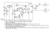
From post #99 (referring to the schematic on that post):
The adjustment labels probably look like they are swapped, but they are not.The adjustment labels probably look like they are swapped, but they are not.
:)
The pot that used to set the threshold for when the input is rising now sets the threshold (range≈3.3V to 4V) for when the input is falling. The pot that looks like the hysteresis pot now sets the threshold for when the input is rising (range≈4.4V to 4.9V).
I explained all this before, but I know stuff like that gets lost in the noise.

Using your schematic as reference, the adjustment procedure is as follows:
1. First, set the 500k pot to its minimum (wiper to left end on schematic).
2. Apply +5V to the MAP input.
3. Check to be sure that pin 1 on the LM393 is low (≈0V).
4. Adjust the 1k pot so that the voltage on its wiper is 3.65V (or whatever you want it to be).
5. Set the 500k pot wiper to the other end (max resistance).
6. Set the MAP input to a voltage below that on the wiper of the 1k pot (somewhere between 0V and 3.65V - not critical), then run it up to the desired threshold (e.g., 4.7V).
7. Adjust the 500k pot slowly until pin 1 goes high.
8. Run input up and down slowly to see that pin 1 switches when the MAP voltage crosses the two thresholds you just est (3.65V and 4.7V, or whatever).
If this doesn't work, You may not hear from me until tomorrow. I'm going out gold prospecting today.:)

BTW, your LED is still upside down, and you have two R4's (the pots).
 
Last edited:
BTW, your LED is still upside down, and you have two R4's (the pots).

Well done in the explanation. FYI I always put resistance on the ground Leg when I do LED's. why? I have no idea. I think I read that on a LED forum somewhere. Works either way unless you think otherwise. I corrected the schematic. Also, do I really need redundant caps (C6, C4) Both going from regulator input to ground? If so, the C4, C5, C6 are all elctrolytics, and C1, C2, C3 are ceramics.

I definitely like this new version that doesnt use the other side of the U1 pins. Saves components. why did you modify it this way anyways? Just curious.

Stu

PS It is a shame, but I have a dozen 10v regulators laying around. But heck, there all under a buck.
 

Attachments

  • Boost circuit-Ron 2010-Mosfet.jpg
    Boost circuit-Ron 2010-Mosfet.jpg
    147.5 KB · Views: 140
Well done in the explanation. FYI I always put resistance on the ground Leg when I do LED's. why? I have no idea. I think I read that on a LED forum somewhere. Works either way unless you think otherwise. I corrected the schematic. Also, do I really need redundant caps (C6, C4) Both going from regulator input to ground? If so, the C4, C5, C6 are all elctrolytics, and C1, C2, C3 are ceramics.
I didn't say that the LED and resistor were in the wrong order. I said that the LED was upside down. What I'm saying is, the anode and cathode are swapped. An LED has to be forward biased, with the anode toward the positive voltage.
I think it will be safe to eliminate C4 and C5.

I definitely like this new version that doesnt use the other side of the U1 pins. Saves components. why did you modify it this way anyways? Just curious.
I modified it because it is simpler.:) IIRC, I originally used the second section because I thought we needed to invert the output of the first one in order to drive the MOSFET.

Stu

PS It is a shame, but I have a dozen 10v regulators laying around. But heck, there all under a buck.
 
I didn't say that the LED and resistor were in the wrong order. I said that the LED was upside down. What I'm saying is, the anode and cathode are swapped. An LED has to be forward biased, with the anode toward the positive voltage.
I think it will be safe to eliminate C4 and C5.

I modified it because it is simpler.:) IIRC, I originally used the second section because I thought we needed to invert the output of the first one in order to drive the MOSFET.

OK, last run through to make sure it looks OK.

BTW, find any gold nuggets~!

Stu
 

Attachments

  • Boost circuit-June 2010-Ron.jpg
    Boost circuit-June 2010-Ron.jpg
    140.4 KB · Views: 142
Schematic looks good.
I didn't find any nuggets. In fact, it was probably one of my worst detecting days in terms of results. The only mildly interesting things I found were a few spent bullets, some .22 shells, an old short rimfire cartridge (haven't measured it yet - maybe .32 or .41 caliber), and 3 unfired Weatherby 7mm magnum cartridges.
 
OK, to pester you one last time (-: I am almost done with my Digikey order. I am getting C3, C4 in Electrolytic Alum caps, 50v for C3, C4. What specs do you recm'd for C1, C2 for the ceramics? Do you think C2 should be a Alum cap as well? I assume a generic 50v radial for either is fine.

Lastly, I have been spending extra dough for multi-turn top adjust pots to get a finer range in adjustments. Do you think it is still a good idea to stick with this, or buy cheaper 1-turn trimmers? I can't tell how precise the adjustments are needed for R4 and R6.

stu
I suspect that eventually, you won't even need a pot where R4 is. A fixed voltage divider of something safe, like 3V, should work fine. Trouble is, we would have to redesign the R5 - R6 - R7 network after you did that, in order to keep the same upper threshold range. In the meantime, 1-turn trimmers should be OK, because I designed pretty narrow ranges for both of them, so you should still get adequate resolution.
I would use this capacitor for all the 100nF parts.


ha~! we do think along similar lines. I had picked this: Digi-Key - 478-5096-ND (Manufacturer - AR205F104K4R) Almost identical except this one has a higher heat range (Automotive (-: )


Good deal on the pots. $1 vrs $10 for a pair is better.

Stu
 
Ron,

In further testing, I want to clarify the operation. When the voltage to Pin 2 is lower than Pin 3, the voltage at Pin 1 is high, Therefore the voltage at the Drain is 12v. This means that a N/C position of the relay is energised and the relay is now operating on the N/O side. Which means the VSV has 12v accross it and is "hot" (or "on" or "open" in my case) Or, the VSV passes air from the "in" port to the "out" port. To clarify, I want the VSV to have 12v applied to it before I reach my 4.7v target because I want the VSV to be "on". I need the air to be passing from the 2 air ports freely of the VSV.

Then when Pin 2 is "higher" than Pin 3, the output of Pin 1 goes low "0". At which time the voltage at the Drain is "0". This "de-energises" the relay. Then the VSV is no longer "hot" and the ports are closed. (No air then can pass from the "in" to "out" port.)

Just to clarify how I "wire" the relay. It can be switched easily to operate in either direction as I said. (N/C vrs N/O). If this is the case, then I would have the VSV connected to the N/O position. If this makes sense.

I can't quite grasp the operation of the Mosfet. When voltage at the "gate" reads .75v should the coil of the relay be 12v or 0v? And when there is '0'v at the gate the relay coil should be the opposite. My brain says a .75v to the Gate means the relay is "hot". But my readings find this to be opposite. I read '0'v at the Gate and the drain reads 12v.

OK, I quite.... Have to read more about this.

Stu
 
You are confusing the heck out of me. You are not planning to drive a relay with the MOSFET, are you?
In your latest schematic, when the input is below 4.7V, the comparator output will be ≈+12V. This has the MOSFET turned ON. The VSV will be energized. When the input exceeds 4.7V, the comparator output will be ≈0V (not 0.75V - where did you get that?). The MOSFET will be OFF, and the VSV will be de-energized.
EDIT: This assumes that the + terminal on the VSV is connected to +12V.
StuHagen's MAP switch schematic.PNG**broken link removed**
 
Last edited:
Sorry, I made a wrong referance and not the Mosfet version here. I was looking at the wrong schematic. You answered my question. The .75v was related to the NPN/Relay version.

I was working on something else that was somewhat identical, and I was going to use the relay for that. So my question was If I used a N/C relay then I would be using the N/O position as described above when the VSV was energized. If the output was +12v on Pin 1 under my threshold, that means the relay would be energized and be "flipped" over to the N/O side. Then when Pin 1 goes to '0' the relay would go back to the N/C position. I wanted to just verify this so I know what Relay pin to wire to. (This also assumes using NPN vrs Mosfet)

Stu


You are confusing the heck out of me. You are not planning to drive a relay with the MOSFET, are you?
In your latest schematic, when the input is below 4.7V, the comparator output will be ≈+12V. This has the MOSFET turned ON. The VSV will be energized. When the input exceeds 4.7V, the comparator output will be ≈0V (not 0.75V - where did you get that?). The MOSFET will be OFF, and the VSV will be de-energized.
EDIT: This assumes that the + terminal on the VSV is connected to +12V.
View attachment 44222**broken link removed**
 
I think you are asking if you can swap N/C for N/O (or vice-versa) on a form C (SPDT) relay when you go from the coil being normally energized to normally deenergized. If that's your question, the answer is yes.
 
Last edited:
I think you are asking if you can swap N/C for N/O (or vice-versa) on a form C (SPDT) relay when you go from the coil being normally energized to normally deenergized. If that's your question, the answer is yes.

OK I thought so. Now, assuming that this boost circuit is "normally on", or the output of Pin 1 is 10v prior to triggering, this means (if I was using a relay) that the coil would be energized.
What would need to change if I wanted the output of Pin 1 to be '0' volts, and the coil not energised? would this require pins #2 and #3 to be reversed?

The reason why I ask this is because I was thinking that it might be better to have the coil starting in its natural "off" state before the circuit triggers it to its "on" state. But I think this would change the dynamics of this circuit. This is for a very similar application where It is important that the relay stays in its off condition before the rising Vsrc triggers it.

Stu

Stu
The simplest solution is to use the second section of the LM393 as an inverter, as we did previously. You only need 3 more resistors (2 for the voltage divider on the input and 1 for the pullup on the output). Otherwise, you have to swap pins 2 and 3, as you said, but the positive feedback still has to return to pin 3, so significant redesign would be required to maintain your hysteresis requirements, possibly requiring even more parts.
 
The simplest solution is to use the second section of the LM393 as an inverter, as we did previously. You only need 3 more resistors (2 for the voltage divider on the input and 1 for the pullup on the output). Otherwise, you have to swap pins 2 and 3, as you said, but the positive feedback still has to return to pin 3, so significant redesign would be required to maintain your hysteresis requirements, possibly requiring even more parts.

So I can use that exact circuit design a page back that uses both sides of the comparator? If so, that is all I need to know.

Stu
 
So I can use that exact circuit design a page back that uses both sides of the comparator? If so, that is all I need to know.

Stu
Stu, each post has a number in the upper right corner. What post is the schematic in that you are referring to?
 
Stu, each post has a number in the upper right corner. What post is the schematic in that you are referring to?

Post #99 that uses the relay. I want this new thing to have the relay "de-energised" before I reach the target "rising" voltage (like 4.7v) Then the relay fires and triggers what I need done.

Stu
 
Post #99 that uses the relay. I want this new thing to have the relay "de-energised" before I reach the target "rising" voltage (like 4.7v) Then the relay fires and triggers what I need done.

Stu
That should work after you swap the inputs on the second comparator.
 
That should work after you swap the inputs on the second comparator.

Cool, just keep all the values the same and swap #2 to #3 vice versa. Reason why is I prefer this to be in the "off" state is for safety in the event the circuit dies on me. I would then be at the default state and the car will continue to run as if this wasnt there.

Stu
 
OK, here's what I came up with. I'm hoping you aren't using the other half of the LM393 for anything. I used it so we can get full output swing on the first one, making the hysteresis easy to attain. If the other section is not available, there are other possible solutions.
I think you were trying to build this with parts on hand. Let me know what you don't have. If it is not difficult to get parts, I recommend the values shown - except for the 2N2222, which might be susceptible to CE breakdown due to spikes on the car's battery rail. Something like 2N5550 would be much better. A small MOSFET could also work, which would also eliminate the need to use the 2nd half of the LM393.
The adjustment labels probably look like they are swapped, but they are not.


Ron,

I can't seem to find this answer. When the output of U4 Pin 7 is at 10v (high), is the coil of the relay "on" or "off". I was testing and the way I see it, when the voltage at the Base is '0' the relay is energized, and I read 12v across the coil. But when the voltage at the Base is 10v, then the relay is de-energised. So my assumption is when voltage is applied to the base of the transitor, it "opens" up the collector to emitter path to ground, like a switch.
Correct?

Stu
 
Status
Not open for further replies.

Latest threads

New Articles From Microcontroller Tips

Back
Top