Continue to Site

Welcome to our site!

Electro Tech is an online community (with over 170,000 members) who enjoy talking about and building electronic circuits, projects and gadgets. To participate you need to register. Registration is free. Click here to register now.

  • Welcome to our site! Electro Tech is an online community (with over 170,000 members) who enjoy talking about and building electronic circuits, projects and gadgets. To participate you need to register. Registration is free. Click here to register now.

Design an adjustable voltage switch

Status
Not open for further replies.
Ron,

Not sure what 2 things your looking at, but this schematic I just uploaded is correct. Help me out a elaborate more on what your saying. It has changed in minor ways a lot over the last year as we tweaked things. But this one is most current.

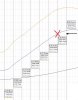
I have attached a snap shot of the actual voltage curve outputted from my car as it relates to the sensor. Where I "want" to be is where the red X is. When I have the Vset at 4.4v to trigger, the cicuit trips fine when the Vsrc gets to it. But If I raise the Vset any higher, the circuit will not trip, even though I know the Vsrc can achieve a higher voltage. As you can see in red, the voltages produced by the sensor can go above where I want to go. So why does it quit "reading" anything above 4.4v set by the Vset.


Stu
 

Attachments

  • Boost MAP Log-post.jpg
    Boost MAP Log-post.jpg
    60.6 KB · Views: 168
Last edited:
Are you absolutely certain that pin 8 on the LM393 is connected directly to +12V? If not, this could explain your problem. If i were you, I would double-check it. There is nothing in the schematic to explain the behavior you are observing.
 
Yep it is. I just assembled another board tonight and it works great on the bench. I did however replaced R1 with a 1Meg to see if that removes the load off the source input. I will report back if the resolves the problem.
 
You either have a bad part, or your schematic does not match your hardware. I'm guessing the latter.

Please explain. I am not following.

In regards to my Post #59 I have solved the problem. I have changed the Vsrc 10K resistor to a 150k and the issue on not triggering at a higher Vset is gone. Must have been too much load for the Vsrc input.

Now I need to get the hysteresis to be greater. The circuit oscillates because when the system triggers, it "re-triggers" because the Vsrc drops about .4v at trigger. I need to get to a minimum of a .40 v hysteresis. What happens is when this triggers at 4.6v the Vsrc immediately drops to 4.2 to 4.3v because that is how the system works. I will try a pot I guess.

Stu
 
Please explain. I am not following.
Simulation of your circuit did not exhibit the problem you were seeing. I realize that simulation is not hardware, but the LM393 spice model kas been very reliable, and reflects reality very closely.
The LM393 input range only extends to Vcc-1.5V, worst case. If you had pin 8 connected to the zener (5.6V) instead of +12V, that could have explained the problem you were having.

In regards to my Post #59 I have solved the problem. I have changed the Vsrc 10K resistor to a 150k and the issue on not triggering at a higher Vset is gone. Must have been too much load for the Vsrc input.
The input bias current on the LM393 is 100nA max. A 150k resistor in series will only change the threshold by 15 millivolts max. Is C3 actually 1nF? A much larger value could possibly explain why 150k solved your problem.

Now I need to get the hysteresis to be greater. The circuit oscillates because when the system triggers, it "re-triggers" because the Vsrc drops about .4v at trigger. I need to get to a minimum of a .40 v hysteresis. What happens is when this triggers at 4.6v the Vsrc immediately drops to 4.2 to 4.3v because that is how the system works. I will try a pot I guess.

Stu
While you may need more hysteresis,I think C3 may make the jitter worse. I would try removing it completely. If you want filtering, use a cap from pin 2 to ground instead.
To increase the hysteresis, change R9 to 100k and R6 to 220k. This should raise the hysteresis to about 450mV.
Also, according to my calculations, R8 should be 27k if you want your trigger level to go down to 4.0V when the pot is bottomed out.
 
Thank's for replying to this "older" thread. It all makes sense in your responses. But since I am an old school EE from the 70's, I am far away from current design. I actually have a freind that wants me to use MOSFETS in lieu of Relay's. But that's another story.

I would like to "repair" this design maybe. When you say that the 150k "repaired" that problem, and if I really used the 1nf. Well, Eric had that suggestion back away's in the thread. Maybe because of a specific problem i was having. But If I go back to the 10K what cap would you recommend I use instead? Or, as you state, maybe remove it all together. I think that was inserted awhile back because of the oscillation I was having. Not sure if I need "filtering" or not. The circuit has tested fine as is. I know at one time that the relay was crazy chattering at the trigger threshold. So maybe the "filter" could solve this. Although as the design stands now, it is not "chattering" just going off-on-off-on slowly.

Now, the hysteresis, you state that your "calculations" show 450mv. Can you share this formula? How accurate is this? Is it this linear in design. I ask this because I could just drop these 2 new values into the circuit and test. Or I can insert a test pot in the R6 location and bench test to get the .40 drop. Then read the pot's resistance. Usually, the hysteresis variable resistance would be just in the R6 location is why i ask because your changing 2 values.

For the sake of under standing this circuit I will try to explain a bit further. This circuit is designed to trigger at a Vset of approx 4.6v signal. This signal is from a sensor that outputs 2v-4.8v range. What happens at the trigger point is it opens a gate valve. When that gate valve opens, the sensor output drops about .4v because itis now reading a lower volume of air. I want it to not retrigger unless the Vsrc drops farther than 4.2v. Otherwise while it is trying to do what itis intended in doing, it will "loop" cycle. Once the car drops back to "idle" so to speak, the process will then start over when the gas pedal is romped on again.

Thanks again.

Stu
 
Last edited:
Thank's for replying to this "older" thread. It all makes sense in your responses. But since I am an old school EE from the 70's, I am far away from current design.
I got my EE in 1966. I retired in 2007. Two old farts.:D
I actually have a freind that wants me to use MOSFETS in lieu of Relay's. But that's another story.

I would like to "repair" this design maybe. When you say that the 150k "repaired" that problem, and if I really used the 1nf. Well, Eric had that suggestion back away's in the thread. Maybe because of a specific problem i was having. But If I go back to the 10K what cap would you recommend I use instead? Or, as you state, maybe remove it all together. I think that was inserted awhile back because of the oscillation I was having. Not sure if I need "filtering" or not. The circuit has tested fine as is. I know at one time that the relay was crazy chattering at the trigger threshold. So maybe the "filter" could solve this. Although as the design stands now, it is not "chattering" just going off-on-off-on slowly.
I would probably take out the cap and see if it still acts the same, but that's just me. You could also go by the old adage, "If it works, don't fix it.".

Now, the hysteresis, you state that your "calculations" show 450mv. Can you share this formula? How accurate is this? Is it this linear in design. I ask this because I could just drop these 2 new values into the circuit and test. Or I can insert a test pot in the R6 location and bench test to get the .40 drop. Then read the pot's resistance. Usually, the hysteresis variable resistance would be just in the R6 location is why i ask because your changing 2 values.
Hysteresis is calculated by simple math. It's just the change in voltage at the noninverting input when the output switches. In this case, first calculate the voltage swing at the comparator output. Since R6>>R5, you can safely ignore R6 for this calculation. The swing will be from ≈0V to ≈1.4V, or about 1.4V p-p. This gets attenuated by the network consisting of R6, R9, and the resistance looking into the pot wiper. The wiper impedance varies from zero to about 8k, depending on where it is set. Thus, your present hysteresis is approximately
Vh=1.4*((R9+Rpot)/(R6+R9+Rpot). This calculates out to be a range of 88mV to 150mV.
Actually, the circuit won't trigger when the wiper is at max voltage, but simulation shows Vh=152mV with the pot voltage at minimum, almost exactly what I calculated.
If you try to leave R9 at 10k, the change in pot resistance will cause your hysteresis to vary even more wildly if you lower the value of R6. That's why I suggested changing R9 to 100k.

For the sake of under standing this circuit I will try to explain a bit further. This circuit is designed to trigger at a Vset of approx 4.6v signal. This signal is from a sensor that outputs 2v-4.8v range. What happens at the trigger point is it opens a gate valve. When that gate valve opens, the sensor output drops about .4v because itis now reading a lower volume of air. I want it to not retrigger unless the Vsrc drops farther than 4.2v. Otherwise while it is trying to do what itis intended in doing, it will "loop" cycle. Once the car drops back to "idle" so to speak, the process will then start over when the gas pedal is romped on again.

Thanks again.

Stu
 
For the sake of testing, I will change R9 to 100K, and then change R6 to 220K. If I decide to leave R9 at 10K...what value "range" do you see for R6? I would rather attempt to keep one of these resistors static, and use a pot for the other. It may make it easier for me to target my desired hysteresis.

Also, if I remove the 1nf what value cap would you rec'mnd from Pin 2 to ground?

Stu
If you leave R9 at 10k, R6=33k will give you a nominal hysteresis of 400mV with the pot wiper at the top, and about 500mV at the bottom. Keep in mind that, with these low values, varying R6 will cause the threshold voltage to change more that if you make R9=100k.
As to the range of R6, it depends on what range of hysteresis you want. I'm not gonna do all the work for you.;) If you're an EE, you can calculate voltage dividers. Either that, or simulate, like I do when I'm lazy or want to confirm my calculations. I recommend LTspice. It's free, and relatively easy to use, although it does have a learning curve, like any software.
Attached is the simulation file I've been using, in case you decide to try it.
I'm not bailing on you - just trying to keep you honest.:D
 

Attachments

  • MAP switch.asc
    2.4 KB · Views: 175
I should add that you should measure the threshold voltage at pin 3, not at the wiper of the pot.
 
I assume this attachment will not open until I install the LTspice? I do not have any file associations with a .asc software.
I agree. In the last year I have read and learned a lot of new stuff. If someone does all the work, great, but I would flunk the class when it came to the "test" ha..ha..
 
I assume this attachment will not open until I install the LTspice? I do not have any file associations with a .asc software.
I agree. In the last year I have read and learned a lot of new stuff. If someone does all the work, great, but I would flunk the class when it came to the "test" ha..ha..
Yeah, a .asc file opens as a simulatable schematic in LTspice, but it's garbage otherwise.

Did you see my previous post?
 
Last edited:
Never mind.............I just loaded LT Splice and all is good. Although they do not have a POT in there inventory that I can see~!
 
Unzip the attachment. Put pot.sub in \lib\sub. Put pot.asy in \lib\sym\misc.
The next time you open LTspice (you might have to close it first), click on the little AND gate icon on the toolbar (Select Component Symbol), then click on Misc. The pot will be there.
 

Attachments

  • Pot.zip
    629 bytes · Views: 135
Couldnt get the "pot" to propogate into the schematic. Will mess around later. I bench tested with only changing the one resistor from 150K to 33K and it appears to work perfectly. I can trigger at 4.5v and the Vref drops to almost 4.0v I tried several voltage levels and they all drop about the same. So I am seeing a bit greater than .4v Which is good. Now I need to try it installed and see if it acts the same. If it still oscillates, I may try a filter cap to ground.
 
Out of curiousity, what is the function of the 400 ohm resistor on the 2N2222 collector? My schematic has the collector going directly to the 1N4001 directly.
 
I am tearing my (little that I have) hair out trying to get more symbols in LTsplice. That "pot" thing wouldnt show in the components list in "misc". There was only 1 POT sym in that zip file. It was just called "pot" and had about 694kb. Can you share with me where to get more libraries? I couldnt find any info on the website.

Stu
 
On another note about my circuit. I do not know if this is because I have partial analog components, like the relay and LED, but this is what i am seeing.

On the bench, the circuit works perfectly. My hysteresis, when set to my desired levels, drops to where I want it. When I set the Vset to 4.6 V it triggers fine. Then immediately, the V drops across the comparitor to about 4.1v. Nice healthy drop and exactly what I wanted. So I go to install it, and it works fine with the exception that at the trigger point, it modulates. In other words, the trigger identifier (LED) goes first "on"--then "off"..then "on" during this transition. (maybe 2 blinks per sec.) Now I do not know why, I am confident that my Vsrc is not dropping all the way down to 4.1v, so I am not sure why it is doing this. I was thinking of the clock speed of the components, the LED, the Relay, and maybe I should install some form of an RC in there to keep the voltage up slightly and have it "drain" slower. Now, I could be totally wrong, and my Vsrc is in fact dropping below the hysteresis of 4.1, then back up, then back down, etc. But I am pretty sure it is not. I also noticed that the LED brightness is dimmer when it is in this modulated process. Other testing at higher levels, the LED is blinding bright. Not sure if this means anything. Would removing or increasing the size of the disc cap between tins 2 and 3 do anything? Or maybe remove as you stated, and drop one in there to ground.

Lastly, is there any reason to change to a V regulator and remove the power to the LM393 from the car's 13.8v source? (poor quality). But continue to use it for the relay and LED, etc.

Always, appreciate any ideas.

Stu
 
Status
Not open for further replies.

Latest threads

New Articles From Microcontroller Tips

Back
Top