Roff
Well-Known Member
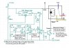
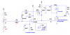
Bipolar transistors (NPN, PNP) are off when no base current flows. They are on when sufficient base current flows. The base-emitter junction looks like a diode. When Vbe (base to emitter voltage) is less than ≈0.7V, the transistor will be off, and no current will flow from collector to emitter. In your circuit, the base voltage of the 2N2222 is approximately at 0V when the comparator - input exceeds the + input, due to an internal NPN at the output of the LM393 which diverts the current through R8, the 3.9k resistor, to ground. When the + input exceeds the - input, the transistor internal to the LM393 will turn off, allowing the current through R8, to flow into the base of the 2N2222. The base voltage will rise to ≈0.7V, and ≈1.87mA of base current will flow ((8V-Vbe)/3.9k=1.87mA). This current will get multiplied by the transistor current gain, saturating the transistor (Vce(sat)<0.2V). This will energize the relay.Ron,
I can't seem to find this answer. When the output of U4 Pin 7 is at 10v (high), is the coil of the relay "on" or "off". I was testing and the way I see it, when the voltage at the Base is '0' the relay is energized, and I read 12v across the coil. But when the voltage at the Base is 10v, then the relay is de-energised. So my assumption is when voltage is applied to the base of the transitor, it "opens" up the collector to emitter path to ground, like a switch.
Correct?
Stu
So - for the second section of the Lm393, when the + input > - input, the relay is energized.
")