If a PCB works best for you, go for it!
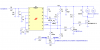
I did breadboard the LM2917 part, and I simulated the 2 transistor driver. I didn't test it on a vehicle, of course.
The MOSFET is fine. Just don't specify it when you go into production.
BTW, if you make money on this, I want a cut!