Continue to Site

Welcome to our site!

Electro Tech is an online community (with over 170,000 members) who enjoy talking about and building electronic circuits, projects and gadgets. To participate you need to register. Registration is free. Click here to register now.

  • Welcome to our site! Electro Tech is an online community (with over 170,000 members) who enjoy talking about and building electronic circuits, projects and gadgets. To participate you need to register. Registration is free. Click here to register now.

Current Sensing circuit idea for 240v ac

Status
Not open for further replies.

pigman

New Member
Hey guys,

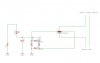
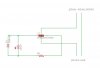
I have a situation that I'm trying to solve. Basically I have a signal powering a Transducer at ~240VAC between 20-40kHz and it operates in bursts for about half a second on and half a second off. What I want to do is put an indicator light on it that senses if current stops flowing and either turn on an LED or turn off and LED. IE if the Transducer fails and the circuit is broken then I need to indicate somehow there is an issue. I have no idea how to do this at the moment as I'm a DC guy normally :(.

Hope you guys can help, I'm sure there is some simple way of doing it but I'm lost.

Cheers in advance.
 
Don't understand exactly what you're trying to do: you say you have a transducer that operates at about 50% duty cycle: that means current (to the transducer) stops flowing every half-second or so. Do you mean you want to sense when current has stopped flowing through the transducer for more than X time (give us the time)? or do you want to know if voltage was applied to the transducer but nothing happened? (Keep in mind the transducer could fail at least two ways: open circuit or short circuit. Or it could just stop working, even though current is still flowing through it.)

What kind of transducer?

Need more info.
 
Last edited:
Per carbonzit more info would be nice like how much current? Other details? However you may be able to use something like this. The lowest current version is 750 mA but the conductor can be looped. They run about $10 USD and should be available from several manufacturers.

Ron
 
Measuring the current of your circuit you'll just know it draws current.

Building an ultrasonic receiver and use an LED at its output you'll know your transducer is working.

Boncuk
 
Yes the transducer runs about 50% duty cycle and operates at 20W. I was thinking something triggered in series with the transducer so it would simply stop flickering the light when there was no current passing through the transducer.
If it fails closed circuit it would overload the transformer and trip my control module's fuse which has its own buzzer and whatnot to alert in that scenario.

That option from Reloadron looks interesting, my guess is it is just an inductor loop of some sort around the wire with a diode to protect the led then straight off to the LED? at 20W 240VAC how many wraps do you think would be needed to excite a small LED? I wouldn't think very many at all? Maybe a small inductor mounted on the PCB and the output to the transducer can loop through that before going off to the transducer? This would be an inexpensive indicator to excite the LED during current flowing? Any ideas on the inductor needed at that voltage, etc?
 
Pigman it is not clear to me if the frequency is 20hz to 40khz or 20khz to 40khz.
The coil you chose is too low an inductance to work at 60 hz, it probably will work at 40khz.
www.coilcraft.com/pwrsense.cfm Here is a collection of current transformers and enough data to get you started.
 
ronsimpson, thanks for that! yes I probably should clarify. The range is from 20kHz to 40kHz. So as I am VERY new to inductors/chokes and current sensing. I'm assuming that the ratio on say the link I provided earlier would be something along the lines of 40:1 and a very low current capacity? but should be enough to run a led? Something like the attached diagram? I guess I just need to know which choke would work.
 

Attachments

  • current-sense-inductor.jpg
    current-sense-inductor.jpg
    19.2 KB · Views: 298
Go back and look at coilcraft. A current transformer has the resistor across the coil. It is not a voltage transformer.
If you have a 100:1 transformer then:
Secondary current is 1/100 of primary current.
Secondary resistance is (100*100=10,000) times. A 100 ohm sense resistor on the secondary makes the primary (high current side) look like a 0.01 ohm resistor.
It is more common to put the LEDs across the secondary with out any resistor. I use two LEDs one for + and one for -. Pick a turn ratio that works for the LEDs. Example. 1mA of LED current through a 100:1 transformer requires 100mA on the primary. 10mA from 1A.
 
What ronsimpson suggested is about the same thing I suggested earlier with one distinct beauty. They offer a selection of coils for current sensing (Current Transformers) over a real nice range of frequencies. I see a few in there that could be a very viable solution. Thanks for the link too.

Ron
 
Ok, so it works....

Here is what I did, I have a 100uH choke that is ~47 turns connected to two leds.
I tested it with a 100Ohm resistor accross the choke and it worked, it is a bit brighter without the 100 ohm resistor. The Transducer is operating at 20W and the leds have been flickering for the last 5 hours. What would be the calculations to ensure I don't overpower the leds in the peak current sensing, as these will be an indication of a failed transducer I wouldn't want to start replacing working transducers because the leds where pushed too hard and failed :(

What would be the formula to figure out the resistor accross the choke and the current resistor for the LED on a 47 turn current transformer. I need to do two one for 50W transducers at 240V and one for 20W transducers at 240V.

Your help is greatly appreciated :)
 
chamelec, thanks for that, he has done something very similar to what I'm planning. I would use a transistor and a safer controlled DC voltage for the LED however in my circumstance the led will be potted in with the transducer and the only power going to the transducer is the transducers power so my issue is finding the right resistor or something to protect the LED while using the induced current from feeding the transducer wire through the inductor.
It works, it was running just two leds on a 100uH inductor with the transducer wire only going through the inductor once and I ran that for about 8 hours or something like that without a resistor on a 20W transducer.
I am just concerned that without a limiting resistor on the led or maybe a cap like in that example chamelec just gave I will end up with the led failing after a month of operation or something like that and that will providing a false failed reading when really the transducer is still going fine...

The ratio of the Current Transformer I have chosen is 50:1 so I just need to figure out what the calculation is to get the value of the resistor to put in place? Anyone able to help out with that? Google isn't really giving me much love. Is everything just calculated at a ratio of 50:1?
 
so I just need to figure out what the calculation is to get the value of the resistor to put in place? Anyone able to help out with that? Google isn't really giving me much love. Is everything just calculated at a ratio of 50:1?

Before you can calculate a resistor, you need to determine the Induced Voltage.
 
chemelec, correct is there a formula that you are aware of for calculating the induced voltage based on the number of turns (ratio) which is 50:1 The operation of the transducer is 240v at 20W and operates between 20kHz to 40kHz which is within the range of the chosen CT.
 
I would suggest you Disconnect the LED and Measure the Voltage.
 
Yes that's is the plan, I am just not going to be infront of the kit again for a few days and was hoping there would just be some formula I could use to derive the figures from.

Cheers
 
Here is something that could be bullet proof. **broken link removed** There are other capacitor/diode supplies for lighting LEDs that are much simpler.

Make sure the BIG Cap is for switching power supplies and you could probably size it so it's just big enough. You'll probably have to lower the value.

When using a LED on 240 AC, or anything above) Vrb -reverse breakdown) you have to have an extra diode in serries with the LED,
 
Last edited:
Ok, well guys I managed to test the voltages and whatnot today and was peeking at 11.9v AC so it was a good low voltage to work with. for those who are interested here is the final schematic to basically power the led while there is current through the choke(current transformer) the values of the components would change based on the current you'd be wanting to flow through the choke. This is for ~50W at 240VAC and the resistor here used I think was to be 200-300ohms with a little led, after the AC to DC conversion and whatnot it worked pretty good at that. C1 is just a 1uF electrolytic to filter residual frequencies out and smooth it all over, mind you it could probably be a lower value... just what I had handy.

Any comments or ideas are welcomed.

Cheers

PS this is a 47:1 ratio, obviously for those wanting to sense lower current flow and still get the led to light up you can just wrap the load to be sensed through an extra time or two to increase the sensitivity. here is a link to the choke I used too.
https://www.altronics.com.au/index.asp?area=item&id=L6517
 

Attachments

  • current-transformer.jpg
    current-transformer.jpg
    31.2 KB · Views: 235
Last edited:
Status
Not open for further replies.

Latest threads

New Articles From Microcontroller Tips

Back
Top