Continue to Site

Welcome to our site!

Electro Tech is an online community (with over 170,000 members) who enjoy talking about and building electronic circuits, projects and gadgets. To participate you need to register. Registration is free. Click here to register now.

  • Welcome to our site! Electro Tech is an online community (with over 170,000 members) who enjoy talking about and building electronic circuits, projects and gadgets. To participate you need to register. Registration is free. Click here to register now.

Creative A520 subwoofer bass controller

Status
Not open for further replies.

stealthjoe

New Member
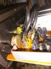
I have a creative A520 5.1 speaker system. Since the last few years, the bass has became virtually non existent or extremely feeble as the bass controller knob doesn't work properly. The knob works only while set at the maximum bass albeit still at a very low punch. It is also too scratchy and tried to clean the potentiometer using a contact cleaner with no results. Does anybody have an idea of the resistance rating of the bass controller potentiometer in the above speaker system and how to replace the existing one? Thanks.

Regards,
Joe
 
The pot being scratchy may mean a DC block capacitor at one of the pot terminals.
Do you have a schematic for the amp?
 
Hi crutschow. Thing is if I twist the bass knob fully to the maximum and hold it I get a decent bass. If I leave it, the bass is low again. Also I am getting a lot of static if I keep twisting it. Reducing the knob values even slightly below maximum makes the bass go almost 0 :banghead:. Hence I think it would most probably be the bass controller knob. Unfortunately there is no schematic available for this device.

I tried measuring the resistance of the pot (by connecting legs 1 and 3) and noticed that it was varying from around 4 Megaohms to around 1-2 Megaohms and fluctuating when the knob was at the highest bass level. Let me know if a bass controller really requires this much resistance rating? Also could I use a less rated pot say around 1 megaohm as I am unable to find a 4 or 5 megaohm one? Thanks.

Regards,
Joe
 
The pot almost certainly isn't that high, if it's reading that high then it looks like the track is broken.

Does it have any numbers/letters on it?, often they have the value printed or stamped on them.
 
Hi Nigel. Tried looking for the values on the pot, but in vain. Have attached a picture of it. Most likely the value might be hidden under the soldered part but not sure though. I too think that the track might be broken. Any suggestions on the recommended pot value I can use (subwoofer has 12 watts rating)?

The pot almost certainly isn't that high, if it's reading that high then it looks like the track is broken.

Does it have any numbers/letters on it?, often they have the value printed or stamped on them.
 

Attachments

  • Creative A520 pot.jpg
    Creative A520 pot.jpg
    116.4 KB · Views: 269
Last edited:
If the pot is a problem, you could try replacing it with a 10k-100k one.
Most solid-state circuits use relatively low impedances.
An audio type (logarithmic) pot would likely be the best type to use.
 
my first guess would be 10k. it doesn't matter much if it's being used in a standard voltage divider configuration. it would matter a lot what the value is if it's in the feedback loop of an op amp. most likely it's being used in the voltage divider role, so anything from 10k to 100k would work.
 
A standard bass and treble tone controls circuit uses 100k linear (not logarithmic) pots and boosts or cuts about 14dB with a flat response when the controls are at halfway. Here is a schematic so check the values of the parts connected to your pots to see if they are the same as this circuit:
 

Attachments

  • Baxandall tone controls.PNG
    Baxandall tone controls.PNG
    11 KB · Views: 222
You're not paying attention properly again AG, it's a PC 5.1 sound system, no tone controls (and never any suggestion of a tone control fault), it's the VOLUME control for the sub-woofer that's faulty.

I also don't see how you can claim that all baxandall circuits use the same value pots and components?, they vary widely depending on the design of the circuit, and obviously where you want the centre frequencies to be.

They can also quite easily use log pots as well, in passive versions rather than active ones - often used in guitar amps etc.
 
How can they say the tiny low-powered woofer is a SUB-woofer? It is a 5.25" little woofer powered with only 12W and the other 5 speakers are little satellite tweeters with 5W each. The controls are not shown so I assumed it has bass and treble tone controls.

Since the highs have a total of 25W but the lows have only 12W then the little 12W woofer must be a one-note boom-box that many people will want to turn down with its own volume control.
 
How can they say the tiny low-powered woofer is a SUB-woofer? It is a 5.25" little woofer powered with only 12W and the other 5 speakers are little satellite tweeters with 5W each. The controls are not shown so I assumed it has bass and treble tone controls.

These sort of things sound surprisingly good, and plugging them in to your flat-screen TV will absolutely transform the sound.
 
Thank you all for your replies. Now it seems like the closest option would be to go for a 10k linear pot. Was initially skeptical about using lower resistance ranges as I am worried about too much signal input to the sub. Further more my queries are as follows:

1) Is there any significance in going for a 100k or 1Mohm as opposed to a 10k pot? Would there be a noticeable decrease in bass quality?

2) Now the major challenge would be in removing the existing pot as I don't see a screw through the knob. My guess is that it could be glued to the pot. I could feel that the pot is firmly soldered to the board and also connected to the knob. Any ideas on how to remove the existing one and replace it with a new one?

Thanks once again.

Regards,
Joe
 
Thank you all for your replies. Now it seems like the closest option would be to go for a 10k linear pot. Was initially skeptical about using lower resistance ranges as I am worried about too much signal input to the sub. Further more my queries are as follows:

1) Is there any significance in going for a 100k or 1Mohm as opposed to a 10k pot? Would there be a noticeable decrease in bass quality?

As we've already said, it's VERY unlikely to be such a high value pot - but without a circuit it's difficult to know exactly what it's doing - but the value shouldn't affect quality regardless.

2) Now the major challenge would be in removing the existing pot as I don't see a screw through the knob. My guess is that it could be glued to the pot. I could feel that the pot is firmly soldered to the board and also connected to the knob. Any ideas on how to remove the existing one and replace it with a new one?

It would be VERY unusual for a knob to be glued on, most likely it's just a tight push fit - but as the pot is broken anyway, levering the knob off can't do any more damage. The pot itself will certainly be soldered to the board, and in the absense of a solder sucker, or de-solder braid, it may be easiest to cut the pots pins, remove the pot, and then remove each pin from the board individually - assuming you can get a pair of small cutters to the pots pins?.
 
If you don't want to mess with soldering on the PCB and possibly damaging it, you might try just cutting the pins, and then using short pieces of wire to connect from the new pot pins to the PCB pins.
 
You do not know the value of the bass volume control. It might be 10k, 50k or 100k.
The bass volume control is probably fed from a series capacitor to block DC. The value of the capacitor is selected to pass bass frequencies to the value of the bass volume control. You must look along the pcb wiring to see the coupling capacitor's value that is feeding the bass volume control.

If you use a 10k ohms log volume control and you want good bass down to 40Hz (the little woofer can't go that low), then the capacitor value must be at least 0.39uF (390nF). If the original bass volume control was 100k then uses a 0.039uF (39nF) coupling capacitor but you use a 10k bass volume control with this capacitor then there will be no bass. If the coupling capacitor value is 0.1uF (100nF) then a 10k bass volume control will produce very weak bass.
 
Comments:

1. The markings might be crypic to you. 103 mean 10K, 10 + 3 zeros ohms.
2. the bottom part (by the pins) has a gap. Spray cleaners lubricants can be directed there.
3. The potentiometer can be taken apart and measured/cleaned. It has tabs on the front.
4. usually the problem is the wiper and dirt.
5. You can measure the element and measure at 1/2 rotation to determine if LOG/Linear
6. If you know a component is bad, cutting the leads before removal helps.
7. You might want to see if it creates a variable DC voltage rather than process the audio.
(Initialy measure the voltage across the ends)
 
You do not know the value of the bass volume control. It might be 10k, 50k or 100k.
The bass volume control is probably fed from a series capacitor to block DC. The value of the capacitor is selected to pass bass frequencies to the value of the bass volume control. You must look along the pcb wiring to see the coupling capacitor's value that is feeding the bass volume control.

If you use a 10k ohms log volume control and you want good bass down to 40Hz (the little woofer can't go that low), then the capacitor value must be at least 0.39uF (390nF). If the original bass volume control was 100k then uses a 0.039uF (39nF) coupling capacitor but you use a 10k bass volume control with this capacitor then there will be no bass. If the coupling capacitor value is 0.1uF (100nF) then a 10k bass volume control will produce very weak bass.
I checked the capacitor values being connected to the potentiometer and there were around 4 capacitors with 2 having 47uF (least value) and other ones having 220uF.

Also regarding logarithmic vs linear pots, my understanding is that volume controls use log pots and tone/bass controls use linear pots. So does log vs linear actually have a perceptible difference in bass quality. Please let me know otherwise which pot type is more suitable?

Regards,
Joe
 
I checked the capacitor values being connected to the potentiometer and there were around 4 capacitors with 2 having 47uF (least value) and other ones having 220uF.

None of those look to be coupling capacitors, more likely power supply decoupling.

Also regarding logarithmic vs linear pots, my understanding is that volume controls use log pots and tone/bass controls use linear pots. So does log vs linear actually have a perceptible difference in bass quality. Please let me know otherwise which pot type is more suitable?

Volume controls are normally log, tone controls are normally linear (although passive designs use log for tone controls as well).

In no case does the type of control affect quality of any kind, it just makes the operation of the control smoother - a linear volume control for example, will have most of it's action at one small part of the track, and have little effect over the rest.
 
The Users Manual for the Creative A520 shows a "Bass Level Control".
A thread about the A520 shows that it uses one or two M51132L volume control ICs where the volume is controlled with DC in a 100k linear pot. The IC converts it into a logarithmic response. Make certain that yours has this IC connected to the bass level control.
I believe (from reading another post on this) this IC is present in the remote volume control wire with a rotary knob (outside the subwoofer) which is used to control the actual volume.

Regards,
Joe
 
Last edited:
Status
Not open for further replies.

Latest threads

New Articles From Microcontroller Tips

Back
Top