0RESET0 said:
OK,
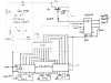
I have gone over some things and I have a question. On a normal counter like the ones I am using, The active output state is high correct? Yes but a counter with AL outputs would be unusual. What is the state of the outputs when they are not active? The attachment may help you.
I thought I read in here that they are floating. No If both of these assumptions are true the would not the same be true for a counter that has active outputs low? If all of these assumptions are true then would a counter chip with the capability of high or low outputs have three possible states, High, Low and Floating? No
Am I totally wrong on this or what? I think I may have confused the issue when I mentioned tri-state. As I see it, a tri-state has a different three states, High, Low and high impedance Yes with the high impedance being applied to all output pins when it is active. This is ambiguous. The Hi Z state is applied when the outputs are disabled. Tri State is used for bus connections, as I explained previously. It does not help you with your situation.
Are these definitions correct? -
Floating - having neither a high or low state but a voltage that falls below the high threshold and above the low threshold. Floating means open. You're right in the case of the PT2262 IC. when open, the voltage is between the upper & lower thresholds. The internal logic determines whether the input is F, H or L, ie. if the input voltage is > the upper threshold, then it is seen as a H, If it is < the lower threshold it is a L. If the input is open (or the voltage is between the upper and lower thresholds) it is F.
High impedance - not connected, the same as physically disconnecting. This is essentially correct. The internal circuitry is disconnected from the output pin. So the output pin would appear to be open if you measured it.
Sean
Sean,
I thought about your project while we were away (not much else to do at mother-in-law's).
After considering various options, I concluded that the configuration I suggested previously is the best, ie. 3 decade counters and decimal displays.
The advantages of this are:-
1. hexadecimal displays are not required.
2. you can have up to 1000 Rx (or 999 if you choose to exclude zero)
3. The Tx circuitry is simple - no BCD/Binary code conversion, etc.
4. It is easier to set the BCD codes (rather than binary codes) in the Rx.
Now I know your objection to this is that you want to use 8 bit switches in the Rx since you want to use all 256 combinations.
I accepted this point originally, but now I'm not so sure.
I assume that the Rx have 12 code setting inputs the same as the Tx. Is this correct?
If so, then to go beyond 256 combinations, you will have to add extra switches. So why not add them at the outset?
Thus the first 4 switches would set the Hundreds digit (in BCD), the next 4 the Tens digit and the last 4 the Units digit.
It is very easy to remember the BCD codes, but not as easy to remember the hex codes.
The DIL switches come in various sizes - 2 way, 4 way, & 8 way, so you could install either an 8 way and a 4 way, or three 4 ways. See
https://www.altronics.com.au/index.asp?area=item&id=S3050 {This is an Australian supplier, but you should be able to buy then in the US also}
You can also buy DIL switches that mount vertically and they have 1/10 th inch spacing between pins. See
https://www.altronics.com.au/index.asp?area=item&id=S3094
Let me know what you think and - assuming I have not missed something - I'll draw a circuit and post it.