Continue to Site

Welcome to our site!

Electro Tech is an online community (with over 170,000 members) who enjoy talking about and building electronic circuits, projects and gadgets. To participate you need to register. Registration is free. Click here to register now.

  • Welcome to our site! Electro Tech is an online community (with over 170,000 members) who enjoy talking about and building electronic circuits, projects and gadgets. To participate you need to register. Registration is free. Click here to register now.

Counter by 4017 stuck!!

Status
Not open for further replies.

cu.chaisit

New Member
Could somebody help me!
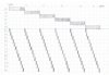
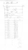
I want to make counter control B1 to B12 continue with A1-A6 see flow chart

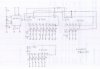
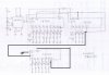
I try by 2 of CD4017 for output of B1-B12 which copy from KINJALGP (post on Feb20, 2003)
I prepare another CD4017 for A1-A6 but I could not continue the circuit
See attached draft circuit

Please help, thanks in advance!!
 

Attachments

  • img189.jpg
    img189.jpg
    81 KB · Views: 359
  • img190.jpg
    img190.jpg
    97.9 KB · Views: 445
hi,
This image clip from the datasheet shows how to cascade 4017's
E
 

Attachments

  • AAesp01.gif
    AAesp01.gif
    30.1 KB · Views: 488
Is the divide by 12 part of the circuit working as expected ? If so then the clock (Pin 14) in of the third 4017 (Shown on your diagram below the divide by 12 stage.) would be connected to the Q0 (Pin 3) of the left hand 4017 on the top left of your diagram. The clock inhibit (Pin 13) of the third 4017 will be connected to ground. Q6 (Pin 5) of the third 4017 would be connected to its own reset pin. (Pin 15)

Les.
 
You can also use a "Mickey Mouse" AND gate made with two diodes and a resistor:
 

Attachments

  • cascaded 4017s-3.PNG
    cascaded 4017s-3.PNG
    14.3 KB · Views: 771
  • Mickey Mouse.jpg
    Mickey Mouse.jpg
    57.3 KB · Views: 280
Did you wire it as shown on the attached picture? if not try this, some times the reset pulse may not give good clock (width). The way you have shown for cascading two 4017 would work wihtout any issue. you can use a RC delay to get improved clock.
 

Attachments

  • img1.jpg
    img1.jpg
    97 KB · Views: 452
Hi, Mbarazeen! yes I have problem just cascading two 4017 not even cascading lower 4017
1. always it start from out1, I want start from out0
2. after all output loop, circuit stop at out0 on 1st 4017, I want continue unless stop power
You can show me RC delay circuit? actually I want timer preset by thumbwheel switch ie: 1=10second, 2=20second

4017 may be getting a clock high at power on, so it may start with out-1. you can better have a start stop switch/ push button and a reset push button . Check your wiring or short between pins due to soldering, as per your drawing it should keep on rolling. time delay is not required if you do not have an issue so you try without it first. I didnt get your point of timer, where do you use it? if you can explain about your application it will help.
 
Dear Mbarazeen
I will check my wiring now I put in easy board;
My application is lamp sequencing 72 lamps formally the signal came from PLC and now the PLC was failure, I want to change by electronics circuit
On photo there are contact relay RD00 to RD11 will change to my circuit B1 to B12 and RD0 to RD5 will change to my circuit A1 to A6
lamp 1 to 12 / 13 to 24 / 14 to 36 / 37 to 48 / 49 to 60 and 61 to 72 --- one side series together control by B1 to B12
another side of lamp group control by A1 to A12

For time delay I feel 555 timer may not much accurate I want circuit like this

Thumbwheel sw---->timer circuit---->pulse----->cpo 4017
 

Attachments

  • scan0018.jpg
    scan0018.jpg
    73.6 KB · Views: 307
so a state change take place in every 10sec or 20 sec as per selection? ie a clock pulse at every 10 sec or at 20sec? timer using 4017 will need a pulse too to count. sounds its for an industrial application otherwise i would suggest to breake a battery operated wach and tap 1 sec pulse form it. You can wire a i sec time base using a crystal oscillator and a counter like 4060. check the data for 4060, it has an oscilator too.
I made a qiuck search **broken link removed**
Was there any time delay in the original design like switch off one set before switch on the other? you are almost near to a working design just put your efforts.
 
cu.chaistit, When the scanning circuit is not active is it in the T0 state or are all of the 72 states inactive ? (None of the 4017 outputs high.) Once started does it continue to loop through the 72 states or does it need to stop after going through the 72 states once ? Some indication of what it is controlling would be helpful. How accurate does the timing need to be ? The reason in my post #3 that I suggested clocking the divide by 6 counter from Q0 on the top left 4016 was to avoid the possible problem with clocking it from the very short reset pulse from the divide by 12 counter.

Les.
 
so a state change take place in every 10sec or 20 sec as per selection? ie a clock pulse at every 10 sec or at 20sec? timer using 4017 will need a pulse too to count. sounds its for an industrial application otherwise i would suggest to breake a battery operated wach and tap 1 sec pulse form it. You can wire a i sec time base using a crystal oscillator and a counter like 4060. check the data for 4060, it has an oscilator too.
I made a qiuck search **broken link removed**
Was there any time delay in the original design like switch off one set before switch on the other? you are almost near to a working design just put your efforts.

mbarazeen, thanks for your advise 4060 and crystal oscillator I will try
The original design are PLC base there are many option many dip switch now those was failure and obsolete, now I try with simple design
 
cu.chaistit, When the scanning circuit is not active is it in the T0 state or are all of the 72 states inactive ? (None of the 4017 outputs high.) Once started does it continue to loop through the 72 states or does it need to stop after going through the 72 states once ? Some indication of what it is controlling would be helpful. How accurate does the timing need to be ? The reason in my post #3 that I suggested clocking the divide by 6 counter from Q0 on the top left 4016 was to avoid the possible problem with clocking it from the very short reset pulse from the divide by 12 counter.

Les.
Les, thanks for come back
1 to 72 lamps should divide by 6
that mean b1 to b12 start with a1 one loop again b1 to b12 with a2 ---> b1 to b12 with a6 ))) this is one loop
 
Ignoring the fact that the divide by 12 counter does not start in the state you require when power is applied to the circuit does the divide by 12 counter work correctly and does it trigger the divide by 6 counter and does that work correctly ? When you have that working we will need to add to the circuit to make it power up in the correct state.
 
Status
Not open for further replies.

Latest threads

Back
Top