perfect.... i got the explanation. Thanks mate.
So, if my design is now not involving any current sources but the bridge, then the resistors being in cloce match will decide the accuracy of the desing.
Am i right?
Yes, other than your calibration resistor (potentiometer) and perhaps a small series resistor associated with it, the other two resistors should be precisely matched with exceptional temperature coefficient. And with the potentiometer calibrated to the RTD at 0 degrees, or with a probe simulator, the potentiometer will balance with the RTD and wire resistance will be accounted for as well.
Other story is the input impedance of my amplifier being very high will not need any componets between the amplifier terminal and the rtd voltmeter probe lead.. right?
I would think not, unless perhaps you want to short protect it some kind of way with a current limiting resistor, perhaps 1kohm of the top of my head. It should have no negative effect either way, except a slight, slight delay in the responsiveness of the probe.[/quote]
What is your feeling about the error that may be there (if it is) in my design due to the lengths of the RTD 3-wires if the length is variable... over the one that the calibration is done for?
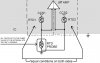
Again, I keep harping on this, I don't advise trying to design a perfectly balanced bridge. All resistors should be precision components for stability purposes, but I do not think you can reproduceably manufacture multiple circuits with varying probe lengths and completely rely on building a perfectly balanced bridge without the ability to calibrate it. You will run into all sorts of problems and become very frustrated. Without designing in some sort of calibration mechanism, I doubt seriously that your circuit would even read 0 degrees with a perfectly balanced bridge. It would take a lot of trial and error in the A/D, amplifier, and microprocessor level, and even then it won't be exactly reproduceable when your next circuit has twice the probe length.
The solution is the variable resistor on the bridge, and calculating the range you will need out of the potentiometer, and selecting a suitable series resistance to go with it. I suggest a 10 ohm fixed precision resistor and a 100 ohm pot because the 10 ohms gives you headroom, the pot can be adjusted to 90 ohms giving you balance at 0 degrees. The 10 ohms would accomodate most wire length variabilities. But perhaps a 20 ohm resistor would be better. This really is something that can't be entirely figured out in this discussion and mght even require some trial and error on the breadboard.
OK, I have just about shared all I know or understand here on this topic. I work with RTDs, but my technical profession is more along the repair and calibration of industrial/laboratory test equipment that involves temperature measurement and control. I only occasionally design circuits for my work, and where temperature control is involved I always purchase DIN PID temperature controllers suitable for the application, with only external circuits, relays, valves, actuators, heat elements, and probe selection being my design considerations.
I have offered all I know. From here out I hope someone else can help guide you if I can't answer questions.
")
