Continue to Site

Welcome to our site!

Electro Tech is an online community (with over 170,000 members) who enjoy talking about and building electronic circuits, projects and gadgets. To participate you need to register. Registration is free. Click here to register now.

  • Welcome to our site! Electro Tech is an online community (with over 170,000 members) who enjoy talking about and building electronic circuits, projects and gadgets. To participate you need to register. Registration is free. Click here to register now.

Constant Current sensor adjustment w/ LM317

Status
Not open for further replies.

MrDEB

Well-Known Member
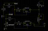
Need to compare the sensor output (junction of R1/R5) using ADC on RA0 with desired temperature setting using 5K pot which will vary the output voltage at junction of R2/R8.
Contemplated using an op amp but then why bother using a PIC. Besides the end result would not what I am after.
Unless someone has a better solution.
The LM317 constant current source is perhaps the best solution for the sensor which is a thermistor HAKKO 907 iron sensor which has a resistance of 50ohms RT and 180ohms at solder melt..
I know this seems kinda convoluted but ??
 

Attachments

  • LM317 sensor adj.png
    LM317 sensor adj.png
    28.9 KB · Views: 304
hi deb,
Look at using a LM393 dual comparator to compare the Tref and Tsensor
 
THANKS Eric BUT
I am wanting to have the LCD display DESIRED TEMPERATURE (RA1) and ACTUAL TEMPERATURE (RA0).
Looks like using the LM393 I only get one output, not two (DESIRED & ACTUAL) plus I find using a simulation (TINA as well as LTSpice the first resistor in the divider dosn't makemuch diffference with a CCS feeding the voltage (R1/R5 and R2/R8)divider
hope this makes sense.
Was contemplating using an LM324 op amp set up as a Howland grounded load constant current source. Problem is the circuits I found were duel supply. Did find one that was single supply but the schematic doesn't jive with the caculations.https://michaelgellis.tripod.com/howland.html
tried different values for R1 but both resistors marked R1 can't be the same. Simulation goes a negative voltage. Unless the PIC ADC can accept a negative voltage?
 
Status
Not open for further replies.

Latest threads

New Articles From Microcontroller Tips

Back
Top