Continue to Site

Welcome to our site!

Electro Tech is an online community (with over 170,000 members) who enjoy talking about and building electronic circuits, projects and gadgets. To participate you need to register. Registration is free. Click here to register now.

  • Welcome to our site! Electro Tech is an online community (with over 170,000 members) who enjoy talking about and building electronic circuits, projects and gadgets. To participate you need to register. Registration is free. Click here to register now.

Circuit to Convert Random Spikes to Square Waves

Status
Not open for further replies.

pnielsen

Member
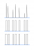
I have an analog signal that looks like a series of unevenly spaced spikes of varying amplitude. I need a circuit that will convert these to a train of digital square waves with s similarly uneven spacing or phase relationship.

I don't want to use a schmitt trigger because it will produce symmetrical square waves based solely on voltage thresholds .

Can anyone suggest a circuit that will suit my application?
 
if I understand correctly, you need some kind of adc module. There are several modules below. You can use them. if you want a wave with a certain frequency in the digital response of each analog signal, you should use the embedded system.
Good luck with it ;)
 

Attachments

  • A-TO-D-PIC1.jpg
    A-TO-D-PIC1.jpg
    43.4 KB · Views: 183
  • schematic1-e1440673838767.png
    schematic1-e1440673838767.png
    149.1 KB · Views: 186
Zero-crossing detector followed perhaps by a monostable? I'm not clear what you mean by 'square waves' in this context.
What sort of spike frequency/interval?
 
I don't want to use a schmitt trigger because it will produce symmetrical square waves based solely on voltage thresholds .
No, it won't. A flipflop will come closer to that, but not do exactly that either.

Please add more detail to your question. All digital logic circuits have input threshold voltage levels, will produce output pulses with equal amplitudes (heights) when those levels are crossed. In this regard, a Schmitt trigger circuit is not different from standard circuits. The only advantage to a schmitt circuit is if the speed (rate of change) of the input voltage as it increases and decreases is very slow.

Both schmitt and non-schmitt circuits can maintain the random nature of the input signal timing (frequencies and pulse widths), but not the various amplitudes. Square waves can be symmetrical (50/50 duty cycle) or not, but they always have a constant amplitude.

A sketch of the input waveform and the desired output waveform will save everyone a lot of time.

ak
 
Thank you for your reply. As requested, here is a sketch of what I am trying to achieve. The original spikes are at the top. The second drawing down would be acceptable. The third is better, provided it does not overly complicate the circuit.

I am hoping to use parts on hand such as common op amps or CMOS IC's.

The circuit into which this will be incorporated is powered by +/-6VDC.
 

Attachments

  • spike_to_square.png
    spike_to_square.png
    10 KB · Views: 194
Thank you for your reply. As requested, here is a sketch of what I am trying to achieve. The original spikes are at the top. The second drawing down would be acceptable. The third is better, provided it does not overly complicate the circuit.

I am hoping to use parts on hand such as common op amps or CMOS IC's.

The circuit into which this will be incorporated is powered by +/-6VDC.

The graph, as you have drawn, is not possible because the output starts reacting before the input starts. It's non-causal. Did you mean to draw it this way?
 
Last edited:
No. The sketch is not that precise. It was just meant to represent the wave forms not the timing. The square waves would be conventionally triggered by the spikes.
 
Then I agree with Alex_t. A monostable vibrator triggered from something like a zero-cross (or some other comparator-type circuit) would get you the second graph.

How did you want to deal with impulses that were closer together than the pre-defined square-width pulse? I think if a regular 555 monostable is triggered in it's unstable state, it just resets the timer and continues to stay high.

You might be able to get graph 3 if you have an op-amp directly charge the 555's charging cap through a diode to make it behave like a buffered peak detector. It would have to be triggered off the 555 timer so it's only charging when appropriate and sounds like a lot of trouble to me. Not sure how well it would work though, especially if the impulse spikes are really short and fast. I also don't think it will be a linear relationship between peak value and pulse width.
 
Last edited:
I would narrow the square wave duty cycle at the monostable for optimal output. Might not catch every spike, but that's OK.

This circuit might be worth a try for the detector, but using my +/- 6VDC supply. https://e2e.ti.com/support/amplifiers/f/14/t/210411

For the third wave form in my sketch, if the original signal was not so "spikey" I might use a single threshold Schmitt trigger. Otherwise, for this type of signal, I have no idea how to make the square wave duty cycle proportionate to the spike amplitude.
 
It appears that the first output is a constant pulse width for each spike. This can be done with a simple monostable circuit. The second output looks like you want the output pulse width to be proportional to the input pulse amplitude. This can be approximated by an integrator followed by a comparator, but the output pulses will be delayed in time (phase shift) slightly, depending on the integrator time constant.

IF the input spikes are variable width as well as height
ANDIF the width is loosely proportional to the height
THEN a comparator will turn out pulses of varying width

ak
 
Thank you. I probably now have enough ideas to breadboard this. I will try just a monostable first (LM555) as most recently suggested. Will get back if I encounter problems.

The spikes are probably too narrow to easily detect any change in width.
 
Might also try a comparator or op-amp configured for high gain. Compare the input signal to a reference, and the output would be high as long as the impulse was greater than the reference.
 
I was more interested in the time domain, i.e. spacing between spikes.

Essentially, I just want to expand the spikes "on" time along the X axis so they resemble square waves with the same uneven spacing as the spikes.

I then intend to low pass filter this to produce an analog-like wave form.
 
Doesn't this just need a monostable multivibrator set to shorter than the shortest gap?

Mike.
 
I then intend to low pass filter this to produce an analog-like wave form.
Why not just lpf the spikes and apply a gain of 2 to the result? If a spike is a true triangle shape then its area is half that of the rectangle (square-wave) which would enclose it, so the lpf output would be roughly half that which you'd get if you lpf'ed the square-waves.
 
to me it looks like you want a pulse width based on amplitude, a microcontroller could do this...
what is the max amplitude of the spikes? .... use parallel resistors to step it down to 5v max .. then you can read it with the ADC ... generating pulse width is easy from there
 
Lots of good ideas here. I will try the monostable first. I have a circuit already drawn up.

When I said "spikes" I meant very short pulses. Prefer no microprocessors. All I need is variable spacing and/or duty cycle of square waves based the random timing of the "spikes".
 
It still is not clear to me why an active circuit is necessary for this. If the spikes are pulses, and you want an output that reflects the variable spacing and duty cycles f the train of spikes, why not just clip the spikes so they all are the same amplitude? Would that plus an output driver of some kind be enough? What is the input impedance of input current requirement of the downstream circuit being driven by the spike circuit output?

ak
 
Perhaps I have not stated it well, but I want to effectively increase the 'on" time of each random spike so each more closely resembles a square wave, all being of equal amplitude. The result would look something like a phase modulated square wave signal.
 
Status
Not open for further replies.

Latest threads

New Articles From Microcontroller Tips

Back
Top