Continue to Site

Welcome to our site!

Electro Tech is an online community (with over 170,000 members) who enjoy talking about and building electronic circuits, projects and gadgets. To participate you need to register. Registration is free. Click here to register now.

  • Welcome to our site! Electro Tech is an online community (with over 170,000 members) who enjoy talking about and building electronic circuits, projects and gadgets. To participate you need to register. Registration is free. Click here to register now.

Circuit Help

Status
Not open for further replies.

skeeterb

Member
some time ago, I posted a circuit that was incomplete. RadioRon helped me out some by giving a logic diagram of the chips I need to make my circuit work. I was asking for the pinout diagram which shows the arrangement of the pins on the IC chip, when ppl griped about me wanting them to do the circuit. I just was interested in the IC pinout instead of the circuit diagram. Looking back at that circuit after time has passed and I temporarily lost interest in the circuit, I have come back to it and want to finish it. In the circuit, when the water level gets below the Upper Water Level Sensor, I want it to turn on a LED, which warns of the low water level in the cell. I changed my mind in the method of turning the LEDs in my circuit, i thought about possibly using a MOSFET or similar chip to control the LEDs. What MOSFETs or similar ICs can I use for that simple switching?
 
skeeterb said:
some time ago, I posted a circuit that was incomplete. RadioRon helped me out some by giving a logic diagram of the chips I need to make my circuit work. I was asking for the pinout diagram which shows the arrangement of the pins on the IC chip, when ppl griped about me wanting them to do the circuit. I just was interested in the IC pinout instead of the circuit diagram. Looking back at that circuit after time has passed and I temporarily lost interest in the circuit, I have come back to it and want to finish it. In the circuit, when the water level gets below the Upper Water Level Sensor, I want it to turn on a LED, which warns of the low water level in the cell. I changed my mind in the method of turning the LEDs in my circuit, i thought about possibly using a MOSFET or similar chip to control the LEDs. What MOSFETs or similar ICs can I use for that simple switching?

Now that you have renewed interest and little more senior than what you were the, please sketch a circuit schematic with components you want to use , and put a brief analysis as you feel it. Then come forward with requests for improvement. Also try to study the deterioration effects of sensors if they are to be in contact with water with the type of water you want to handle( i meant the conductivity and hardness factors of the water at your location under concern),

this much can be expected , i feel.
 
Last edited:
mvs sarma said:
Now that you have renewed interest and little more senior than what you were the, please sketch a circuit schematic with components you want to use , and put a brief analysis as you feel it. Then come forward with requests for improvement.

this much can be expected , i feel.

Here is the circuit I had up to the last time that I posted about this circuit back in July. Oh, and I'm also including some new work ideas that I have come up with recently for hydrogen cell design. I'm restructuring my circuit diagram, but until I get some info for MOSFETS and IC Pinouts, It's gonna be a while before the final draft of the circuit comes out.

Edit: I've been doing some searching and found the pinouts for the 4011 and 4093 Logic ICs. I was recommended those 2 ICs, but looking at the pinouts, I probably use only 1 IC for my needs because of the number on Inputs and Outputs available on the chip. Should I use the 4093 w/ Schmitt Triggers or the 4011 IC? Now all i need to get some info on what MOSFETs i can use to act as switches for my indicator circuit, which is shown in the circuit diagram, for when the upper and lower water level sensors pull low, AKA get below the lower water level sensor.
 

Attachments

  • CircuitChanged 001.jpg
    CircuitChanged 001.jpg
    372.5 KB · Views: 536
  • hydroxy pressure 2.jpg
    hydroxy pressure 2.jpg
    245.3 KB · Views: 383
Last edited:
Can anyone help me figure out this Logic Diagram, so i can figure out which inputs and outputs to use and which ones to leave alone and just connect to ground.

Edit: here's more info from RadioRon when he originally posted this diagram

RadioRon said:
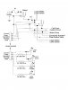
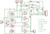
This is a bare bones logic diagram, not a complete schematic. It is essential that this circuit be powered from a regulated DC power supply, which requires that you choose a suitable voltage (which depends on the electronic parts you choose), and then include a 78xx voltage regulator IC, where the xx is your voltage, and then wire the output of this regulator to the logic ICs that you use.

The inputs and outputs are Active High, or in other words, positive logic. This is not the only way to do this and may not be the most convenient. It assumes that your water level sensors put out a high voltage when they sense water and a low voltage otherwise. It also assumes that the sensor high voltage is within the input voltage range of the ICs that you choose. The output is active high but you will need a high current switch to power the pump and valve. I have not shown this high current switch.

Here is some theory of operation. G1's output will only go high when both of the inputs are low (i.e both sensors are "dry"). This is our signal to start the pump, so we call this "pump start". G2's output will only go high when both sensors are "wet" so we call this "pump stop". G4 and G5 are configured as an RS latch which is a two state circuit that will remember the last instruction given to it (hence the name "latch"). When it gets a high on "pump start" then the output "to water pump switch" will go high. When it gets a high on "pump stop" then the output will go low. Nothing happens when an input high to this latch goes low again, that is, the latch remembers that there was an input high before. The resistor/diode/capacitor circuit on G3 input generates a short pulse on "pump stop" when you first turn the power on, to insure the latch powers up in the right state under all conditions.
 

Attachments

  • student_circuit.JPG
    student_circuit.JPG
    121.6 KB · Views: 348
Last edited:
Hi Skeeter

In the diagram that I provided some time ago, you will notice that there are little numbers beside the wires going into each gate symbol. These numbers refer to the pins on the respective ICs. This circuit MUST use two ICs, you can't use one or the other of the 4011 or 4093. The reason for this is that I have chosen two very different kinds of gates. The gate symbol with a straight line on the left is a NAND gate, while the one with the slight curve on the left is a NOR gate. These two types operate very differently and you have to be very careful when substituting one for the other. So, referring to the diagram, G2 and G3 must be in the 4093. You provide power to the 4093 with Vsupply at pin 14 and GND at pin 7. Pins 1, 2, 12, and 13 must be grounded. Otherwise, G2 is pins 4, 5, 6 and G3 is pins 8, 9 ,10 as shown in the diagram. Gates G1, G4 and G5 must be in a 4011 IC. The 4011 is powered with Vsupply at pin 14 and GND at pin 7. You must ground pins 1 and 2. Otherwise, hook up the pins as numbered in the diagram.

In general, you should make sure that your inputs to this circuit do not go higher in voltage than Vsupply nor should they go lower in voltage than Ground.

I hope this helps.
 
Thanks Ron, I appreciate your help, that will help me with my circuit. I now realize I should have been searching the web for the pinouts for the ICs myself, when I was begging for them back in July. I guess time away from this project has made a difference in my mindset for this project. I wasn't sure what you meant in the logic diagram, because I'm still a NOOB when it comes to designing circuits. You may have noticed another thread that I started here that mainly focuses on the indicator circuit of my project. I've changed how its gonna work, but I'm slowly working it out. I was planning on using transistors and a 555 Astable circuit to make the Warn (Orange) LED flash when the Refill (Yellow) LED is lit. I was trying to figure out a way to switch it from steady burn: Refill LED off, to flash: Refill LED lit. I'm not begging for a circuit diagram, cause I already have some of it already planned out, since I'm gonna use an Astable 555 circuit, and transistors. Its the arrangement that I'm just puzzling over.
 
Here's a little more complete version of the circuit using the reference that Ron gave me, so see what you think and see what changes need to be made. This image excludes the indicator portion that I am working on in a separate thread here. Tell me what you think about this circuit and i need to change to look better or what might be needed. I'm working on adding the indicator circuit, but until I get that portion done, the circuit diagram is going to be incomplete.
 

Attachments

  • ControlCircuit.jpg
    ControlCircuit.jpg
    190.8 KB · Views: 249
Last edited:
Circuit Help (Fixed Circuit)

I know I'm bumping this thread, but I noticed that some gripes have been posted about me spreading out my information and request to a bunch of different threads. So, I am using this old thread to update everyone on the status of my circuit. I have redesigned it using Eagle and have tried to reduce the size of the circuit schematic diagram and have actually made some progress. I have also created a board layout for my circuit. I am posting both here to see what everyone thinks of the redesign using Eagle.
 

Attachments

  • Control Circuit.JPG
    Control Circuit.JPG
    74.6 KB · Views: 292
  • Control Board.JPG
    Control Board.JPG
    49.2 KB · Views: 286
Wierd Results

I know I'm bumping an old thread again, but this is relevant to this line of thought. I downloaded Multisim and putting the circuit together as I think it should go according to the simple logic diagram that RadioRon posted. I have been getting some weird results from the simulator in Multisim. I use a 12 V input to the circuit and the output of it is 15 V. Also the indicator I put on the output of the circuit comes on with one switch I use to simulate the upper and lower water level sensors of the cell.I have attached 2 pictures I copied from Multisim, the first is the circuit as it is at rest. the second is when I running the simulator with the upper switch open. Everyone may notice the difference of these circuit diagrams from the ones previously posted. That is because I changed the wiring to more follow the logic diagram posted by RadioRon.
 

Attachments

  • Control Circuit 1.PNG
    Control Circuit 1.PNG
    37.5 KB · Views: 373
  • Control Circuit 2.PNG
    Control Circuit 2.PNG
    37.4 KB · Views: 265
Last edited:
Status
Not open for further replies.

New Articles From Microcontroller Tips

Back
Top