Continue to Site

Welcome to our site!

Electro Tech is an online community (with over 170,000 members) who enjoy talking about and building electronic circuits, projects and gadgets. To participate you need to register. Registration is free. Click here to register now.

  • Welcome to our site! Electro Tech is an online community (with over 170,000 members) who enjoy talking about and building electronic circuits, projects and gadgets. To participate you need to register. Registration is free. Click here to register now.

Circuit Help - 4017

Status
Not open for further replies.
Please sketch how you connected pins 13 and 14 of the 4017, and the switch.
 
switching circuit

heres part of my camera cctv switcher to show what i was talking about regarding the use of a 4093.........the circuit also caters for switchbounce removal.
 

Attachments

  • switcher40172.jpg
    switcher40172.jpg
    67.2 KB · Views: 162
Last edited:
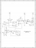
You could use a 555 in monostable operation with a very low frequency, and connect the 555 to the 4017's clock input. Then use all the LEDs you need on the Q0-Q9 outputs, and connect the last output (if use 2 leds, connect 2 of them on Q0 and Q1, and conect Q2 to reset that way it resets and only goes through the sequence of flashing 2 LEDS). There you go that may work, dunno I hardly use 555 in monostable.
 
Status
Not open for further replies.

Latest threads

New Articles From Microcontroller Tips

Back
Top