Electro Tech is an online community (with over 170,000 members) who enjoy talking about and building electronic circuits, projects and gadgets. To participate you need to register. Registration is free. Click here to register now.
Welcome to our site! Electro Tech is an online community (with over 170,000 members) who enjoy talking about and building electronic circuits, projects and gadgets. To participate you need to register. Registration is free. Click here to register now.
hello, anyone. Recently, i want to design a circuit of 0.75V reference voltage. i have researched the majority of the IC manufacturers' material, but i still cannt find a suitable design for my circuit.
could anyone offer some materials about the circuit design? thanks.
the circuit needs to be high precision. yes, using two resistors can get what i want. but i think it's not a good approach. cause this method cann't achieve high precision. and the high precision is quite important for me.
to be honest, i donnt think this point: .1% resistor. it seems that it almost has no influnce to ma circuit design. thanks.
by the way, do you discover a direct reference IC : 5V input, 0.75V output?
No. As far as I know, there is no such thing as a .75 volt reference. That's why everybody in the world knows how to use resistors to get the voltage they want from a reference that is not EXACTLY .000% what they want.
No. As far as I know, there is no such thing as a .75 volt reference. That's why everybody in the world knows how to use resistors to get the voltage they want from a reference that is not EXACTLY .000% what they want.
There are many ways to design a circuit of .75 volts, but you can't buy one, exactly one, and nothing except ONE part to do it. You said at one point, "high precision". If a precision of one tenth of a percent isn't what you want, what do you want? Do you want .7500000 volts with only one part?
The lowest voltage reference is 1.25V which is pretty standard and can be found using Google.
If you put a potential divider consisting of 100k and 150k on the output you'll have 0.75V, unfortunately the output impedance will be equivalent to both resistors in parallel but this can be reduced to around 1Ω by adding a unity gain buffer.
The potential divider formula is on Wikipedia so the same technique can be used for any voltage.
thanks for all the replys. the precision is sufficient for my design.
another question: i want to use the NE555 chip to produce 120khz square waveform, can the IC work? my mean is : is there a frequency limitation? like the highest frequency, lowest frequency etc..
thanks for all the replys. the precision is sufficient for my design.
another question: i want to use the NE555 chip to produce 120khz square waveform, can the IC work? my mean is : is there a frequency limitation? like the highest frequency, lowest frequency etc..
I tracked this guy down on another site and found the answer. Dioded Incorporated makes an adjustable shunt regulator that starts at .6 volts. ZXRE060. He'll still have to use resistors, but this low of a voltage regulator is news to me and apparently a lot of other people.
I tracked this guy down on another site and found the answer. Dioded Incorporated makes an adjustable shunt regulator that starts at .6 volts. ZXRE060. He'll still have to use resistors, but this low of a voltage regulator is news to me and apparently a lot of other people.
hello, anyone. Recently, i want to design a circuit of 0.75V reference voltage. i have researched the majority of the IC manufacturers' material, but i still cannt find a suitable design for my circuit.
could anyone offer some materials about the circuit design? thanks.
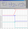
When using a resistive divider to create a lower reference voltage from a higher one, say 0.75V from a 1.25V reference, you need to consider that the resistive divider makes a reference voltage source which is degraded because the resistors used in the divider effectively put a resistance in series with the lowered reference voltage.
Look at the sim attached. I purposely choose low value divider resistors that draw 10mA from the 1.25V input reference source. I set up a test where a 10K load is switched to the tap of the voltage divider at the 1s point in the simulation to see how the 10K load effects the voltage at the tap. Note that connecting the 10K to the tap causes a -2.2mV downward shift in the output voltage.
You could ask what the jump would be as a function of the divider resistance, the load resistance, and if the load resistance varies with time. If the load resistance is steady (time invariant) then you might be able to compensate for the effect of the load by just making R2 slightly bigger, such that when R2 is paralleled with 10K, the voltage at the tap is exactly 750mV.
If the load does vary, then to determine the variation at the tap voltage it is helpful to replace the circuit with its Thevinin equivalent, which calls for creating a voltage source with a voltage source in series with source resistance. Note the alternate circuit in the simulation. Note that the behavior is identical to that of the original circuit; open circuit voltage is 750mV, which drops to 747.75mV when the 10K load is connected.
To replace the original source/voltage divider with its Thevinin Equiv, reduce the source voltage from 1.25 to 0.75, and replace the divider with a resistor which is R1R2/(R1+R2).
Note that you could predict the drop by doing the following calculation: The 30Ω Thevinin source resistance and the 10K form a secondary voltage divider: The output voltage is = 0.75*10000/(30+10000) = 0.75*0.997 = 0.7477.
This shows the general approach how to calculate this for any similar requirement. Rules of thumb. Make R1,R2 as small as possible consistent with power requirements so that the Thevinin source resistance is low compared to the load resistance.
If you need better regulation than can be achieved with just resistors, there are ways to use an opamp to make a precision reference source derived from a higher one.
This site uses cookies to help personalise content, tailor your experience and to keep you logged in if you register.
By continuing to use this site, you are consenting to our use of cookies.