Continue to Site

Welcome to our site!

Electro Tech is an online community (with over 170,000 members) who enjoy talking about and building electronic circuits, projects and gadgets. To participate you need to register. Registration is free. Click here to register now.

  • Welcome to our site! Electro Tech is an online community (with over 170,000 members) who enjoy talking about and building electronic circuits, projects and gadgets. To participate you need to register. Registration is free. Click here to register now.

Cheap / Low Power Simple Freq. Counter

Status
Not open for further replies.
To me it looks grounded ("Clear" on your divider 390...IC6B pin 14 which in the spec sheet is identified as "Master Reset"). How do you speak of it being inverted? It has the Ground signification on it.
 

Attachments

  • ground significa&#1.JPG
    ground significa&#1.JPG
    30 KB · Views: 184
Last edited:
Anyone on my previous inquiries re driving LEDs ??

The Motorola spec sheet for the 4543 (14543) notes an LED display could be driven, but the IC only supplies about 10ma per segment. Not much. It suggests it's "Phase" be connected to low for C/C Leds, and high for C/A Leds, but it also suggests for higher draws (VDD <= 10 V or Iout >= 10 mA) that a bipolar transistor be used. Anybody, I'm sure a Darlington driver array (such as a ULN2003a, for 5V devices) would do "the trick", but I don't need 500ma for each segment. How about a package that supplies less current, w/o me having to do 35 transistors individually ?? If I do the Qs individually, which (TO-92) might someone suggest for this common cathode task?


Anybody on the Bi-Polar transistor array driver thing, for less than 500ma per channel (segment)? What about a TO-92 which would be ideal w/o extra discreet components?

My speaking of extra discreet components doesn't encompass the LEDs current limiting resistors...
 
Last edited:
To me it looks grounded ("Clear" on your divider 390...IC6B pin 14 which in the spec sheet is identified as "Master Reset"). How do you speak of it being inverted? It has the Ground signification on it.

Oh that's the last counter for expanding sample rate only. But your right I forgot about that one. All the rest are inverted with the latch & load signals.
 
With my ten second gate, I would have the display blank for ten seconds, then display the most recent latched/decoded binary values for ten seconds. I want it to display for ten seconds, blank (long enough to load the BCD codes), and then start counting all over again (which would require the J-K to reset, but since it's being used in toggle mode, I would actually have to reset it's clock input back to low, hence, MR the divider 390s). Any idears ??

Any ideas on resetting the dividers but allowing enough time for the Latch/Load, or if that will even work? Should I Master Reset the divider's 390s with the transistor delay circuit that resets the counter's 390s? Might this cause endless oscillation of the J-K? I'm not much into flip-flops, especially in toggle mode, but does the J-K change it's state when the clock input signal goes high? Or does it do it on each change (output goes high on clock's high in, and low on low in)? If it only "flips" it's output when the clock input goes high, then resetting the dividers won't do any good because it would still be ten seconds before the clock input goes high again...

How about driving LED's folks??? An array of bipolars w/ low throw (50ma), or a TO92 transistor that I could do it with only utilizing the LED's current limiting resistors??? This can't possibly be all that difficult for you pros out there to answer, is it???
 
Last edited:
I wonder why the notice of a reply to this thread ended in my SPAM folder?
 
I wonder why the notice of a reply to this thread ended in my SPAM folder?

I don't know because I did replay to his question and it is not here????? Well let me do it again. It was kinda long. So, Dragon my friend. What a J-K flip flop does in the toggle state is that every low to high transition of the clock input will cause the Q outputs to toggle or change their state. So NO, it does not oscillate. What it is being use for is to create a gate signal that is precisely what you want it set on, 1KHz, 100Hz, 10Hz, 1Hz resolution. The reason it is needed is that the decade counters do not produce a 50 percent duty cycle from their Q outputs. Only Binary counters do that. But the decade counter will divide by 10. Its just that the Qd output will not be useful as a gate pulse because it is not 50/50 duty cycle. So let's suppose I want to read down to 1Hz and I have divided the counter's crystal reference clock down to one 1Hz. I can now run that one Hertz signal into a J-K flip flop setup for toggle mode. We run the 1Hz signal into the J-K and it will do a binary divide by two just as if I was taking the signal off the Qa output of a Binary counter which in both cases will be a 50% duty cycle where the output frequency is .5Hz. Because it takes both the high and low portions of the cycle to create this frequency which is 2 duty cycles, a positive and a negative, we need only one half of the cycle for our gate signal. This will occur at twice the frequency. So 2 X .5Hz = 1Hz. So we have a 1Hz gate pulse.
 
What a <74LS112> J-K flip flop does in the toggle state is that every low to high transition of the clock input...So NO, it does not oscillate...

I wasn't asking if it, the J-K flip flop in toggle mode, oscillates. I understand it cycles according to the received pulse transition, every time it receives the clock signal (with dividers it would only receive this signal on every "completed" division <the last divide-by-10 in the overall division>, and it's new state <high or low> would hold until the next low-to-high transition). I'm wondering about if my resetting the last 390 divider's MR pin (whose Qd output drives the J-K which drives the transistor delay circuit that supplies the high signal which resets the counters and I would like to utilize to reset all of my dividers), would cause oscillation of the J-K, because I would need to reset it (the J-K) as well through the delay circuitry...

From what you write, with a 50/50 cycle of the J-K, the J-K would not oscillate because of a 390's reset (Qd will go low, and J-K will stay high long enough for the transistor delay to reset the counters/dividers until the next high). But by doing the 50/50 thing, I would have to wait 20 seconds for each updated 10 second gate sample to be displayed. I would like the 10 second gate to be updated around every 10 seconds with everything immediately reset for a new sample. If I "reset" the J-K, it's "high" output duration would be very short. The moment I supply reset "low" through the delay circuit (via an additional bipolar transistor) to the J-K, the J-K would no longer supply the high TO the delay circuit, so the J-K may either not get reset or may endlessly oscillate <the longer durationed "low" signal out of the J-K may sink/drain the capacitor in the delay circuit and then things wouldn't reset or do something else awry>, thereby "forcing" me to allow the J-K to run "endlessly" (50/50 toggle mode), which is not what I want to do.. Understand where my concerns originated??

The reason it is needed is that the decade counters do not produce a 50 percent duty cycle from their Q outputs. Only Binary counters do that. But the decade counter will divide by 10. Its just that the Qd output will not be useful as a gate pulse because it is not 50/50 duty cycle.

I'm aware the 74LS390 internally resets the counter every ten pulses, but with my long gate signal, I will have to reset them every cycle of the gate, or there may be up to tens of thousands of clock cycles already sitting in my dividers from the previous gate sample, which would thereby reduce <each gate sample> and cause a different reading, even if I was to supply a steady frequency as the signal being read ("true time division"). You don't need to seem to worry about that too much (why the divider MR is always low), since you're only dividing-by-10 once, and it would only have 1-7 cycles sitting in that divider with each gate sample. You're measuring much higher frequencies than I, and I'm aware of the need of the J-K...in your circuit (1KHz or 100Hz gate)...so, do you think I could do without a toggle flip-flop (and maybe replace it's low-to-high transition via a bipolar transistor, a different mode of a flip-flop, or a one-shot timer set at a longer duration than the gate, any of which would be reset/restarted by the high-to-low transition from Qd in the last divider 390), since I'm only sampling every ten seconds (0.1Hz gate) and a measured signal around 7.5KHz? I would think that would give enough time <to load the latch/decoder/driver and reset the counters & dividers>, what do you think ??? [[[your driving a pulse rate at a 50% duty cycle (5 of every 10 clock pulses) and with your 1KHz <undivided> gate, that reduces real time of the J-K going and staying high, to every 0.005 seconds...but I would be doing a 20% duty cycle via Qd with a 0.1Hz gate which would increase real time of a high output to a much longer duration than your circuit operates at <2 seconds>...]]]
 
Last edited:
Alright. Your kinda getting off base toward the end. The J-K flip flop's "preset & clear" functions are asynchronous meaning they happen immediately. They do not wait for any signal or gates to change. They do it instantaneously. So as far as frequency goes and where you begin your sampling, does not matter. The frequency you are to measure is far faster that any gate or latching signals. Whenever it begins it's count, it will be accurate.
Absolutely do not use a one shot! A one shot may trigger at the right starting point but the end will be determined by an RC time constant. It would be a dreadful mistake! The J-K flip flop would be your best choice but you still have one wasted gate. Now you could use other sorts of binary counters like a 74hc191 but you would have even more wasted outputs. I think what you are failing to undersand is that the J-K flip flop gives you true 50% duty cycle squaring of the signal. But the frequency is divided in half also. The reason for this is because the Q outputs ONLY transition on the leading edge of the clock input. Therefore, we are not concerned with the pulse duration or trailing edge of the previous gate which of course is the Qd output from the '390. All we have to know is that the leading edge will be an accurate X10 division which it is. So the J-K flip flop will not transition until the next accurate X10 division. So each high and each low Q output will occure at a X10 division which gives us a perfect 50% duty cycle. So now your gonna ask why would it give me a divide by ten display if it gets divided by 2 at the end. Right? Follow me here. It's because, when it goes through the AND gate, the frequency can only pass through the And gate 1/2 of the time. The other half of the "gate" pulse will be negative and therefore will not pass the frequency to the output. So, the positive pulses into the AND gate (from the J-K flip flip) occure at twice the speed of the divide by 2 division done by the J-K. Therefor you are measuring at the exact frequency produced by the Qd output of the last decade counter.

Did I clear that up for you? I hope so ;D
 
Last edited:
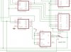
OK. First, let's look at your schematic and how it operates (from what I can see), and you tell me where I'm wrong. Then I'll explain (after you respond), what it is I need to do.

The J-K flip flop's "preset & clear" functions are asynchronous meaning they happen immediately. They do not wait for any signal or gates to change. They do it instantaneously.

I am aware of this. The J-K's reset only takes place when it goes low, hence the term "toggle" (it automatically cycles <from low to high, or from high to low> with EACH clock input at the clock input's low-to-high transition). Your circuit keeps the J-K's reset high at ALL times, so your J-K does this toggling of the outputs on each clock's low-to-high. But this means if the J-K is already high, it will stay high until the next clock transition (from low to high), and vice-versa. The clock signal is your gate sampler (duration of incoming signal sampling). Your J-K endlessly oscillates it's output, going high every OTHER low to high output of the clock signal. I am also aware that the J-K is used to generate a square wave signal to filter the clock signal. If the clock is coming in at 100Hz (divided), then the J-K's square wave goes high for .01 secs and then low for .01 secs (50/50), because it toggles ONLY on EACH low-to high transition, and each of these transitions changes the output state of the J-K to the opposite of what it currently is.

The following "textual flowchart" is w/ use of the divider (100Hz), and the J-K's output is high...

The Qd outputs a clock (low->high) transition, so the J-K's output now goes low and then...

1.) The AND severs the signal which allowed the sampled signal to be routed to the counters. The transistor delay circuit will start charging. The L/D/D remembers the most recent BCD from the counters (due to LD <latch disable> now being low), because that BCD was read through the L/D/D's last high. The BL (blanking) is lifted (now low), and the display shows the L/D/D current stored count.

2.) The transistor delay thresholds / sends a high signal to reset the counters. The purpose of delay is to allow time for BCD to be loaded to the L/D/D before the counters are reset.

3.) Your divider does not reset, because MR (pin 14) is always low (but the counters DO reset <via pins 2 & 14> because they are controlled by the transistor delay). Therefore, you will always have a value between 0 and 9 within your divider, no matter what state the J-K is in, because that divider is tied directly to your clock signal and MR is always low.

4.) The sampled value is displayed for the .01 second duration that the J-K remains low.

The next clock (low->high) transition arrives, the J-K's output goes high and then...

1.) The AND starts allowing the sampled signal to be counted. The BL (blanking) will be enabled (now high) and the display will not show any value.

2.) The sampled value is tallied by the counters.

3.) The L/D/D "tracks" the changing BCD (LD is high), for storing when it's LD goes low.

4.) Your divider's Qd stays low and eventually goes high (at some point), but not necessarily every 10 cycles (re CL always tied to the clock signal and MR <pin 14> always being low), because it never gets reset. This plays little factor in your circuit because your utilizing the circuit to count millions of cycles, and the divider would at a maximum, yield little variation, because your also sampling it at a very high rate (100Hz, every <other> .01 seconds).

5.) When the divider Qd goes high again (after .01 seconds <or so>), the cycle starts over.
 
Last edited:
Well it does reset. The output of the J-K resets them all. The transistor circuit is not a delay. It is an inverter. I just did not want to put another chip in it. If you use an '04 in place of the transistor it will do the same thing.
 
Well it does reset.

Are you talking about the J-K? It doesn't "reset", it cycles between high and low every OTHER tenth of a second (with the divider), upon EVERY ten clock transitions from low to high. My point is, that the J-K toggles between low and high on each transition it receives, so the J-K output (no matter how much division takes place) goes from low to high on one transition, and then from high to low on the next.

Also, your divider is not resetting. Pin14 is always low in your circuit, and the chip's spec indicates it needs a high to reset. Since you're allowing the J-K to 50/50, you always get the start of the sampling each time your divider cycles through 10 clock pulses (actually 20, because it's sampling for ten and then displaying them for ten, re the L/D/D blanking on high and latching on low which is cycled by your J-K). This non-reset may not matter much in your circuit due to the high frequencies sampled and the super short gate, but if I implement a ten second gate at 7500.0Hz with 4 dividers I could have a significant variance. I would also have a blank display for ten seconds while sampled, and then a set-in-stone reading for the next ten seconds.

Your divider is also always connected to the clock, so if there is hesitation between reset and latch and the clock happens to feed a pulse or two into the divider in that time, it would shorten the gate duration (of sampling). I realize the Q is inverting, but it is also delaying ever so slightly in order to allow the L/D/D to load the BCD before resetting the counters. Otherwise if this all took place at once, the BCD would reset and the L/D/D would always have all lows to latch.

Maybe I just don't get all of your circuit, but what I've wrote so far is what I see in the schematic and what I've researched on the IC spec sheet truth tables. I do appreciate all of your help, but I simply need to try to do one thing. Turn the schematic you have into a counter that will give me 9999.9Hz maximum; by reducing the gate to ten seconds so I can get a decimal value on the last 7-segment (through additional dividers), resetting the counters and dividers so I can start a new sampling immediately without having to wait 10 seconds while the last sample displays (it samples through one cycle of the J-K, and displays through the other), and one last thing that nobody has responded to...turning the L/D/D to drive LEDS through a bipolar style annex (simple TO-92s or Octal Drivers) with the least amount of discreets as possible.

My only other thought of this all, is that maybe I will ten-fold my clock (I'm sampling) and have your counter cycle every second (instead of ten), and then divide the clock by ten to drive the dividers that are already driving the stepper motor (555@7500Hz=> /10 => /10 => yields a stable timeframe for the stepper motor (cir 75Hz that I can change by thousandths of hertz as needed for proper timing through the 555's multiple "coarse/medium/fine" tuning potentiometers). What do you, or anybody else out there (everybody else who has been hiding through all of this!), think?
 
Last edited:
Real quick. You are not taking into consideration that what the J-K clocks off of is reset at the proper time so the J-K is right on time. It is OK. You are over analyzing it. If your interested in building this simple counter, just build it. It works fine. You'll see. It's always nice to have a good rf front end amplifier which I did not include. Other wise you need input signals that must cross CMOS logic level thresholds.
 
Status
Not open for further replies.

Latest threads

New Articles From Microcontroller Tips

Back
Top