Continue to Site

Welcome to our site!

Electro Tech is an online community (with over 170,000 members) who enjoy talking about and building electronic circuits, projects and gadgets. To participate you need to register. Registration is free. Click here to register now.

  • Welcome to our site! Electro Tech is an online community (with over 170,000 members) who enjoy talking about and building electronic circuits, projects and gadgets. To participate you need to register. Registration is free. Click here to register now.

Charger Circuit Required

Status
Not open for further replies.

burhanmz

Member
I have got 2 maintenance free lead acid batteries. 12V 40AH each.. they are connected in series to UPS. problem is, the UPS's charger doesn't charge the batteries quickly enough..

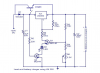
can someone give me schematic to a 24V @ 6~10A smart charger circuit for the batteries (one with full brute charge and then float charge, so that when the battery is fully charged only a trickle current is applied )..

i have searched it on google, but no helpful results.. can someone help me here?
 
forgot to tell u.. i already got a transformer 240 to 24V ac 15amps out

i really want to get over with it... so please help
 
so basically
my charging voltage should be 14.7x2=29.4V
and floating voltage would be 13.6x2=27.2V ????????????????
 
Yes, adjusted for battery (probably ambient) temperature. The references contain the temperature adjustment factor. Best reference is the Data Sheet for the batteries you are actually buying. The description of the charging algorithm applies for all lead-acid chemistry batteries.
 
Last edited:
bah.. this is becoming so difficult... all the circuits i find are for 12 volt charging (14.7v) ...

my battery is YUASA SMF NS40ZL

if i built my own circuit, i'd put a voltage regulator like lm350, with a transistor for increased current, and another transistor to detect float charger being applied.. for which i might just use a comparator.. and then the protection diodes would mean i'd have to increase my charging and float charging voltages by an equal amount of all the diodes drop in series with the batteries. Ahhh..

hasn't someone already gone through all this.. am i the first?
 
bah.. this is becoming so difficult... all the circuits i find are for 12 volt charging (14.7v) ...
...

hasn't someone already gone through all this.. am i the first?

Sure. Just write a check.
 
really funny..
well this just means i'll have to design one.. and then probably u'll criticize on it, once i post it here!
 
Bur most people do the smart thing and buy a commercial charger, it's almost always cheaper than building one yourself.
 
...
well this just means i'll have to design one.. and then probably u'll criticize on it, once i post it here!

We aim to please :D

Basically, you need a regulated power supply capable of putting out two preset voltages, Vcharge and Vfloat. The supply should have current-limiting built in; both to protect itself and to keep the max charging current within the range specified by the battery maker.

If you want automatic recharging, then you will need a controller which will switch the supply from Vc to Vf when the charging current tapers to the appropriate level. I have several circuits do to this.

If you are willing to recharge with manual intervention, then you have to watch the charging current and then switch from Vc to Vf by flipping a switch or turning a knob. :)
 
Last edited:
what would this circuit do.
the website where i took it from said, it will supply 13.8 volts with full current rating of lm350 i.e 3A until the battery is charged, after which the output voltage will drop by Vref and provide a very low current of milliamps. As soon as the battery discharges, the Vout will once switch to 13.8 volts to charge the battery.

is that so?
 

Attachments

  • untitled.PNG
    untitled.PNG
    155.3 KB · Views: 1,396
Status
Not open for further replies.

Latest threads

New Articles From Microcontroller Tips

Back
Top