Continue to Site

Welcome to our site!

Electro Tech is an online community (with over 170,000 members) who enjoy talking about and building electronic circuits, projects and gadgets. To participate you need to register. Registration is free. Click here to register now.

  • Welcome to our site! Electro Tech is an online community (with over 170,000 members) who enjoy talking about and building electronic circuits, projects and gadgets. To participate you need to register. Registration is free. Click here to register now.

Change the frequency in LT1249?

Status
Not open for further replies.

mading2018

Member
Hello,

What I understand it is possible to change the frequency externally by changing the components parameters, but I am not sure what to do to adjust the frequency. Can maybe someone show me how it will be implemented in the demo circuit?

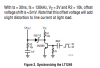
According to the data sheet, it says that "The LT1249 can be externally synchronized in a frequency range of 127kHz to 160kHz"
So what I understand, it is possible to reach 150 kHz.

I found LT1248 as well (operating for 300 kHz), but I wanted to try if it possible to change the freq in LT1249 first.
 

Attachments

  • freq.png
    freq.png
    34.2 KB · Views: 225
  • LT1249_TA01 (5).asc
    5.2 KB · Views: 227
Last edited:
Range 127 kHz to 160 kHz includes the frequency of 150kHz, so yes it is possible, if you adhere to all the stuff the datasheet has to say about doing so.
But I don´t really understand why you´d want to do it.
 
I just want to increase the switching frequency, cause the selected components are calculated for 150 kHz, thats all.
 
On a quick scan of the datasheet I think you need an external 150kHz oscillator, meeting certain conditions, to drive the IC if you want to change its frequency.
 
On a quick scan of the datasheet I think you need an external 150kHz oscillator, meeting certain conditions, to drive the IC if you want to change its frequency.
Hmm, so simply maybe connecting a voltage source with 150 kHz to the IC (at CAout)? Or do I need to build an oscillator for that?
 
Build an oscillator and follow the example in the data sheet. (real life)
For SPICE, you can make a 150khz voltage source. (again see how the data sheet connects the signal to the IC)
 
also don´t forget the datasheet states "The width of the synchronizing pulse should be under 60ns."
 
I tried to follow the data-sheet but I am not sure if I am on the right track. Could you please check the circuit I have? What I understand I need this "Synchronization circuit" to reach 150 kHz.
I added a PWM with 66.66 us as the time period (150 kHz).
 

Attachments

  • OFF_ACDC_boostPFC_LT1249.asc
    5.5 KB · Views: 223
I added a PWM
No. It's a plain vanilla voltage source. You need to set its rise, fall and on parameters for correct sync. Note that the on time must be less than 60nS.
 
Can I do like this instead? I just ignored the GTDR, and directly connected a voltage source to the switch with 150 kHz.
 

Attachments

  • OFF_ACDC_boostPFC_LT1249.asc
    5.1 KB · Views: 202
Like that, the IC is doing nothing useful. No PFC, no voltage regulation.
 
Like that, the IC is doing nothing useful. No PFC, no voltage regulation.
Oh, okay I should have known. But can you please show me how I should adjust the circuit in #8?
You said I need rise, fall and on parameters. You mean something like this: PULSE(0 15 5.002u 1n 1n 2.5u 6.66u)?

I am a bit in a stress these days, cause I need to show some results of a working PFC.. I would be so thankful if you could help me out.
 
I modified the circuit a bit, but it seems still not to work. The simulation got stuck somehow.
Not sure if its 150 kHz now
 

Attachments

  • OFF_ACDC_boostPFC_LT1249.asc
    5.6 KB · Views: 198
Errors: That will make smoke in real life. (lucky for you SPICE does not make smoke and fire)
You have not learned when I hand you answers. So this time you need to find the answers.
1) Pick different diodes. D2,3,4,5 What voltage do you need? What current do you need? Simple answer.
2) Pick different MOSFET? Why will this transistor break?
3) U1 will never output a signal to Q1. Why? Not easy to see. You can find why.
4) You do not understand "common mode power line filtering". Until you understand what 33mH+33mH does to the power line I think you should not have filtering. (remove it) This is a lesson for a different day.
5) There are more problems but this is good for now.

Alec_t, We are at about 1000 posts and the same errors happen every time. I am not a good teacher or these problems would not happen every time. I think Mading2018 must work to find the errors, to help memory.
Also: I think you or I should teach why PFC. What is PFC? Maybe on a new thread.
 
You mean something like this: PULSE(0 15 5.002u 1n 1n 2.5u 6.66u)?
Why did you choose 2.5u for the on time? The datasheet specifically says no more than 60nS for synchronisation.

Ron, I'm happy to try to help with the PFC bit, but I'm learning as I go myself. I've no practical experience with it.
 
datasheet specifically says no more than 60nS for synchronisation.
that's the trick question, does the datasheet talk about the input signal, or the result after the buffer circuit and why? I doubt the two would be the same, or even close.
 
The datasheet sets out the sync requirements on page 7, using the circuit in Fig 2.
 
that's the trick question
The 60nS is made by 80pF and the Base-Emitter junction.
The input signal can be square wave. Only the rising edge is important.
upload_2018-4-17_12-14-26.png

You must use the right type of diode here. (diode on the collector of the transistor)
 
PFC stuff would be excellent! I could do with some lessons H I N T
 
Status
Not open for further replies.

Latest threads

New Articles From Microcontroller Tips

Back
Top