Continue to Site

Welcome to our site!

Electro Tech is an online community (with over 170,000 members) who enjoy talking about and building electronic circuits, projects and gadgets. To participate you need to register. Registration is free. Click here to register now.

  • Welcome to our site! Electro Tech is an online community (with over 170,000 members) who enjoy talking about and building electronic circuits, projects and gadgets. To participate you need to register. Registration is free. Click here to register now.

Change the frequency in LT1249?

Status
Not open for further replies.
PFC stuff would be excellent! I could do with some lessons
If a resistor is across the power line the voltage and the current are sine wave. PF is good.
Add 4 diodes makes no change. The current on the power line is a sine wave. PF is good.
Adding a capacitor on the output of the diodes causes high current at low duty cycle. Bad PF.

upload_2018-4-17_22-0-47.png

A IC looks at the power line voltage. It also looks at the power line current.
The IC has a job to make the current match the voltage.
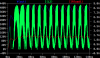
The transistor current is like a sine wave. (chopped)
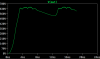
The inductor current is a sine wave. (depends on what type of PWM but close to sine wave)
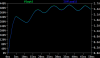
At the peak of the line voltage the boost circuit only boosts a small amount in voltage. (large current)
At a low point in the line voltage the boost must boost from 10V all the way up to 400V. (low current)
The duty cycle changes depending in the amount of boost needed at this power line phase.
The IC most important job is to watch the current.
The IC has a low level job. To keep the 400 volts at about 400. The error amplifier is very slow. It will take about 8 to 10 cycles of the power line to change the 400V.
----edited----
One last thing. A normal PWM will try to pull current all the time. This will result in bad PF. The IC pulls power in a sine wave. ( two half sine waves)

Thanks for the Likes! Ron
 
Last edited:
1) Pick different diodes. D2,3,4,5 What voltage do you need? What current do you need? Simple answer.

Diodes that can withstand at least 4 A and 230 V.

2) Pick different MOSFET? Why will this transistor break?

I think its because it have only a Vds of 100 V. So it should be higher.

3) U1 will never output a signal to Q1. Why? Not easy to see. You can find why.

Hmm, its not easy to see for me. I think something is wrong with the connection.

4) You do not understand "common mode power line filtering". Until you understand what 33mH+33mH does to the power line I think you should not have filtering. (remove it) This is a lesson for a different day.

I thought they were used to filter unwanted noise from the signal on the line. But yes, I removed it from the circuit.

5) There are more problems but this is good for now.

Okay, we can check them later.

Yes , it would be great if you can teach me PFC more. I need more knowledge about that. One of my supervisor said also it can be good to skip all the IC-circuit and only connecting voltage sources that are sending PWM to the switches, would that be good enough? Maybe I do not have to a PFC for my case ?
 
1) 230V is true. Normally we use 800V diodes. Because the power line is very unpredictable. Lightning strikes and heavy loads turning on/off cause spikes on the power line.
2) The output of circuit is 400V You should use a 600V part.
3) The schematic I was looking at had no "Vcc".
4) Yes they are used but not the way you are using it. 66mH + C + C makes a LC that resonates.
4a) There are two type of noise. Common mode and Differential mode.
4b) What you made is probably common mode. The two inductors are on the same transformer. They are couples. .K L1 L2 1
1410_emc_en28_3.ashx

Watch in "dots" on the transformer. The transformer is wound so the load current does not see the 30mH=30mH. (a 30mH 10A inductor is very large) The load current in one side is (+) and (-) in the other. So the load sees almost 0mH. (maybe 100uH) K=1 or K=0.999 The load sees C-100uH -C. Not C-66mH-C.
learn-more-common-mode2.jpg.aspx
 
1. Okay, so it's better to choose diodes that can withstand higher voltages, just in case. So its okay if I pick a 800 V diode? Would 600 V diode also work?
2. Aha, okay, I see.
3. You checked this one earlier? (see attached file).
4. Aha, okay, I must have mixed them up. So the EMI filter design is wrong. It should look something as you showed me earlier.
How do I choose the values for the EMI filter? Are there any equations, or typical values that can be selected? As you said I think I calculated the components (for a CM filter) value according to this source:
https://www.fairchildsemi.com/techn...gnetic-Interference-EMI-in-Power-Supplies.pdf
 

Attachments

  • OFF_ACDC_boostPFC_LT1249.asc
    4.8 KB · Views: 177
  • emi filter.jpg
    emi filter.jpg
    11.8 KB · Views: 246
I missed that totally, thank you. I have added a power source now, and I get a voltage over 600 V.
I think I can adjust the output voltage by changing the R5 and R6.

But since I wanted to obtain 150kHz from the IC (Rset=10 kohm, Cset=1000pF), I tested with LT1248 as well. I changed the components of the transistor and diodes, and it seems to look better.
 

Attachments

  • output LT1249.png
    output LT1249.png
    28.9 KB · Views: 245
  • output LT1248.png
    output LT1248.png
    41.5 KB · Views: 243
  • ACDC_PFC_LT1248.asc
    6.9 KB · Views: 198
Found some interesting things.
Here you see the PFC circuit starting up. It starts working at about 100mS. See the L1 current in red. It is sine wave rectified. That is what we want. Sine voltage sine current.
upload_2018-4-18_20-40-14.png


upload_2018-4-18_20-44-9.png

Added D7. Not needed for SPICE but in real life it helps at power up. (I have built these :))
(C6 * Rload) Increased the capacitor. The RC time constant should be the same.
Removed Q3, V3. I do not know why but it caused the error amplifier to not work right. Went back to 100khz.
 

Attachments

  • upload_2018-4-18_20-42-53.png
    upload_2018-4-18_20-42-53.png
    7.7 KB · Views: 264
Aha, I see. The voltage output looks good, and the inductor current looks good as well.

Okay, so for the EMI filter, its just enough to add the capacitors only ? Since as you said before that the load sees almost 0mH, right?

Hmm okay, so the calculated values is not accurate and needs to be changed for the simulation? Is that strange or have I calculated the values totally wrong?
I thought they shouldn't changed too much, but just a bit maybe.

What about the the other file, LT1248. Is it possible to maintain 150 kHz in frequency with that file?
 
Oh, sorry. I forgot to attach the file. my misstake. I got this graph when I tried to do something similar as the LT1249.
 

Attachments

  • ACDC_PFC_LT1248.asc
    6.9 KB · Views: 189
  • output.png
    output.png
    64.7 KB · Views: 263
Last edited:
What about the the other file, LT1248. Is it possible to maintain 150 kHz in frequency with that file?
Should be. The rated maximum frequency is 300kHz.
 
Status
Not open for further replies.

Latest threads

Back
Top