Continue to Site

Welcome to our site!

Electro Tech is an online community (with over 170,000 members) who enjoy talking about and building electronic circuits, projects and gadgets. To participate you need to register. Registration is free. Click here to register now.

  • Welcome to our site! Electro Tech is an online community (with over 170,000 members) who enjoy talking about and building electronic circuits, projects and gadgets. To participate you need to register. Registration is free. Click here to register now.

Building a hall effects shaft encoder?

Status
Not open for further replies.

kentken

New Member
I need to build a sensor that will measure the turns of a shaft.
I was thinking of using a ring magnet or gear tooth system. then reading the rise and fall of the mag field. then converting it into a length, that the wheel on the shaft moves.

Has anyone done this?
It is on a piece of farm equipment; vibration, and dust.
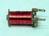
I was thinking something like the picture, incased in plastic or epoxe

Or is there a place to get such a thing?
The shaft is 3/4 dia, maby a hub??
**broken link removed**

Thanks
Kent
 
That type of sensor is used a lot in industrial environments. Here's a link to a product from Cherry Corp. which might be just what you're looking for:
**broken link removed**
Instead of using a ring of magnets, this one uses the teeth on a gear to sense the speed of rotation.
Hope this helps. JB
 
I was thinking that first, but the sensors are expensive, and I would have to find a gear, and figure out how to mount it.

I believe with a ring made of magnets, I can use a normal solid state hall sensor, from allegro or hamlin.

I then would count the pulses, to calculate the length passing under the shaft.

Has anyone used this type of sensor?
Tips, Issues?


Thanks
Kent
 
First of all, the sensor for sensing the teeth on a steel gear is CHEAP. You can roll your own. It's nothing more than a bar magnet with several hundred turns of fine wire wrapped around it. A few dips in shellac and a good coating of epoxy will give it good environmental protection.

If all you need to sense is a full rotation of the shaft, it shouldn't be a problem. It's rare to find a shaft that doesn't have some periodic abberation in its rotation, whether a flat or a setscrew. Or you can attach a magnet.

If you need incremental shaft information, that's a different story. But how can setting up all those ring magnets be easier in the long run than slipping a commercially-made gear on somewhere along the shaft?

Now, if you need absolute position information even when the shaft is stationary, you will need either optoelectronic or Hall-effect sensors. Opto is usually ruled out in dusty environs. I was going to help a guy add a lot of electronics to his big sawmill and was working around that problem, but he died before the project really got started, so I didn't mess around with it anymore. He was wanting to replace the limit switches that he was using because they wouldn't adjust for creep in the hydraulics. It didn't take me but a few microseconds to realize that opto wasn't going to work unless everything was enclosed, which made everything a lot more expensive, mechanically.

Dean
 
I suggested the unit from Cherry because most people seem to want a "plug-it-in-and-go" solution.

Dean Huster said:
First of all, the sensor for sensing the teeth on a steel gear is CHEAP. You can roll your own.

True, Dean. Here's how I made one once. I took the coil out of an old relay with burnt-up contacts (6vdc coil, I think). I used the iron pole piece and attached a (strong) little speaker magnet to the backside. When you bring the metal end opposite the magnet near a rotating gear, you get a waveform out of the coil as each tooth passes by. If you want to get pretty, squared pulses, you'll need to add some conditioning electronics. Look below and see a photo of it. (I never did dip it in epoxy or anything like that, it was just an experiment. It did work real well, though.)

Dean Huster said:
It's rare to find a shaft that doesn't have some periodic abberation in its rotation, whether a flat or a setscrew.

Or a keyway ...

One problem you might have with anything magnetic is that it will probably pick up all kinds of little magnetic particles over time ...

JB
 

Attachments

  • pickup.jpg
    pickup.jpg
    15.3 KB · Views: 800
the easiest , would be as suggested above, use some metallic protrusion on the shaft to " drive " a coil pick up. this is very common in vehicles. I have worked with tachographs in the past, and these all required a sinewave input realtive to the speed of the vehicle. Sometimes we used the vehicles sensor on the ring gear, other times we used a pick-up coil near a universal joint. these sensors are cheap, reliable and mechanically very durable. You can even place them near a balancing weight that is attached to the shaft, or bolt heads whe the shaft is attached. Any spinning ferrous object protruding off the shaft will vary the output of a coil pick-up.
 
When going down the Hall sensor road there is no need to use a 'ring' of magnets. One tiny magnet is sufficient to count shaft revolutions.
I have fitted two magnets (to maintain balance) on the front of the tail shaft of my car, these, coupled with a hall sensor, are the input to the cruise control. It would be hard to find a more dirty enviroment than the underside of a car, the Hall sensor works from a 3 mm gap to the magnets.
Klaus
 
The problem with that is that the shaft runs to slow.
I need to count the length of each stroke put into a haw bale, that are about 36" long.
The shaft has a 8" or so star wheel that runs allong the hay bale.
So the Cir is about 25", at a min resulution of 1/2" I would need 100 pulses, to be added up.

I am starting to think this might be more bother then its worth. But if you have some good ideas...

Thanks Kent
 
kentken said:
The problem with that is that the shaft runs to slow.
I need to count the length of each stroke put into a haw bale, that are about 36" long.
The shaft has a 8" or so star wheel that runs allong the hay bale.
So the Cir is about 25", at a min resulution of 1/2" I would need 100 pulses, to be added up.

I am starting to think this might be more bother then its worth. But if you have some good ideas...

Thanks Kent

Kent, I have absolutely no idea what a haybaler looks like, let alone knowing how it works :wink:
Assuming there is a slow revolving shaft and you wish to know resolutions to 1/100th of its position.
Also assuming you could bolt things to that shaft, how about getting an old truck flywheel from the wreckers and use the teeth of the starter ring gear with the sensors mentioned by Dean above? There must be close to 100 teeth on the ring gear, though I never counted them. If its out of a truck with a tacho then the sensor should be there as well.

The other thing is, that shaft must be driven from a much faster spinning motor. If there are gears (not belts) used for speed reduction you could perhaps sense the fractional turns of the output shaft by counting full turns on the input side.

It does seem a lot of bother
:)
Klaus
 
Basicly, hay goes in front, a large plunger pounds it into a chamber that has hydralic squeased sides.
At the right length twine is pulled around and tied.

If anyone wants a video clip, I will make one.:wink:

I am also thinking that the gear would work better. Right now I have so many projects to finish up.
The flywheel Idea sounds good, but, I don't have to room and I believe they have more then 200 teeth.

thanks for help
kent
 
Status
Not open for further replies.

Latest threads

New Articles From Microcontroller Tips

Back
Top