Continue to Site

Welcome to our site!

Electro Tech is an online community (with over 170,000 members) who enjoy talking about and building electronic circuits, projects and gadgets. To participate you need to register. Registration is free. Click here to register now.

  • Welcome to our site! Electro Tech is an online community (with over 170,000 members) who enjoy talking about and building electronic circuits, projects and gadgets. To participate you need to register. Registration is free. Click here to register now.

Bistable on/off-circuit.

Status
Not open for further replies.

Dix

New Member
I thought it would be easy...! I have some electronics (a project) that needs a regulated voltage, from a 3.3 V regulator (KA278R33). Connected to ca 12 V.
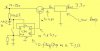
I also want to switch this electronics on and off with a toggling flip/flop. Therefore, the flip/flop always needs voltage. In order to make the circuit use very low current when off I thought of using the 74ac74 or the hc74. But, those boys mustn´t be given more than 5.5/6 volts so then, i thought of a simple resistor and a zener diode of around 6-7 volts because if the resistor is a high one, say like 50000 Ohms, then the zener voltage will drop to around 5 Volts which matches the flip/flop. (Zeners need around 5 (oh a little spider on my keyboard).. mA. ) The zener<->resistor is connected to the unregulated voltage, which is always on. And of course, on the flip/flop the Q inv. output is connected to the D input etc and Q to an npn(-darlington) transistor in front of the KA278R33.
The regulator is a low drop type and needs >3.8 Volts. The darlington´s
double Vbe voltage is ca 2x0.2=1.2. So the input darlibgton base voltage
has to be 5 Volts or more.

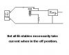
Well... does anyone know of a certain voltage regulator or circuit that has all of this in a chip? I have searched extensively with no results. I think it´s strange. I got hold of LDO-regulators from Fairchild, (KA)278R05 that has an enable input. However, in off-mode it draws 2.5 mA as measured.
Does anyone know of a regulator with a much less current need while being in the disenable mode. It shall handle ca 1A.
A regulator that would switch on/off by a clock pulse and have a very very low off current and also a low quiscent current, say 10 mA would be acceptable.
I guess there is no circuit like that.
Anyway, any comments are welcome. Any other ways to do it?

Regards,
Dick - Sweden
 
Hello,

You need to think before you write a request for help like the one above. If you want any help, please re-write in a clear orderly manner which we can understand. Sorry to be a nit-picker, but I read it twice and it makes no sense to me.

Steve
 
What about this?

Scubasteve said:
Hello,

You need to think before you write a request for help like the one above. If you want any help, please re-write in a clear orderly manner which we can understand. Sorry to be a nit-picker, but I read it twice and it makes no sense to me.

Steve
I might have been overly descriptive above. So sure. There are 4 blocks mentioned above. A resistor-zener diode, a flip/flop-circuit, an npn transistor and a voltage regulator.

The flip/flop is powered by the zener. The resistor above the zener is connected to the car battery +. The car battery + is also connected to the collector of the transistor. The Q from the flip/flop is connected to the base of the transistor. The emitter of the transistor is connector to Vin on the voltage regulator. Vout of the regulator is connected to.. whatever there is.

Sorry I don´t have an image but if you don´t get the picture this time I don´t think you´d be able to read a decent book.

Short, clear and with fullest sense.
 
still thinking about this.
 
Hm

john1 said:
still thinking about this.
And I´m still thinking it´s weird that there is no known ic-circuit in the market that would do the job. All the "modern" (crap) equipment for the last 15 years are mostly switched on by a micro switch. What kind of circuitries are there in all those rice-plastic-products?

Only 4 pins would be fine in such a circuit, imagine a TO-220/263 etc
with a Vin, Gnd, Vout and a switch input (-->toggling flip/flop on the chip). (The other contact of the switch would be connected to + or gnd). And when it´s off it would draw only a few µA. In other words, a cmos-baby.

Actually, I am willing to pay for information about which semiconductor
manufacturer who produces such a circuit, or.. the name of it, IF there is.
I have spent too much time looking for it. Although meanwhile, I have found other interesting circuits.

Or could I do the job with 2 circuits?
 
Hi Dix,

I'm still not quite sure what you want.
Hope the spider is ok.

Not sure if you want the supply to be removed or not,
not sure what kind of pulse you're using to toggle.

What would be ideal??

Ideally, the stabilised output would switch off when
a pulse comes in, and use no current.

Then switch back on when a different pulse comes in,
OR maybe the same pulse again???

What exactly do you want?

Regards, John
 
Not all Bi-stables take current in the off position.
 

Attachments

  • Bi-stable.jpg
    Bi-stable.jpg
    7.2 KB · Views: 811
Here you go

Ok, now nothing is left to (lack of) fantasy anymore. (Advice; read some good books too, not just Data books ;-)

And so to be clearified. I would like to see this, or equivalent, in an existing chip and as said, I would pay for getting that info.
 

Attachments

  • power.switch.circuit.jpg
    power.switch.circuit.jpg
    26.8 KB · Views: 956
Oh, I see what you want now. If you want a toggling function, you will need a flipflop in the configuration as you suggested, there is no way around that. I am curious to see why you have chosen that particular zener diode in place of a regulator, which isn't any more complex then a zener/resistor and will offer superior performance.

As for your scheme to drive the flipflop, it will not work all of the time! You need to debounce this switch or else it will be a game to which state it will be after you pressed the switch. There are several circuits and even chips that will do this function effectively.

You cannot find a chip for every application, especially uncommon tasks such as what you are doing. If you gave us your actual application we probably could suggest something better for you. Until then, good luck

Steve
 
Scubasteve said:
Oh, I see what you want now. If you want a toggling function, you will need a flipflop in the configuration as you suggested, there is no way around that. I am curious to see why you have chosen that particular zener diode in place of a regulator, which isn't any more complex then a zener/resistor and will offer superior performance.

As for your scheme to drive the flipflop, it will not work all of the time! You need to debounce this switch or else it will be a game to which state it will be after you pressed the switch. There are several circuits and even chips that will do this function effectively.

You cannot find a chip for every application, especially uncommon tasks such as what you are doing. If you gave us your actual application we probably could suggest something better for you. Until then, good luck

Steve
Why would curiousity arise?! Zener diodes are cheaper.
This is to be used in several products and it will probably be changed a little here and there but basically the same. Cost is a factor. Only if I was given free components I would have used other types.

The supply voltage to the f/f is of course not critical. I tried 50k for the resistor and "7.5 V" zener which gave ca 5 Volts. And the micropower references cost a lot lot more than the standard models. But why waste money at all? The voltage at the transistor emitter gets to around 4 Volts when using a darlington, which is a condition in order not to draw too much current from the flip/flop which otherwise might lower the voltage below 2 Volts. Maybe it could do anyway because the flip/flop did the job even at 1 Volt. But the darlingtons available as cheap as standard transistors so I rather use them.

As I said, the f/f-circuit shall draw as little power as possible as long as Q=L, shunted to the zener voltage circuit. I measured some 0.2 mA which
could be ok.

The RC-combination i tried as a first try was 1 MOhm and 39nf. If the resistor is too low it will affect the zener voltage when pressing down the switch.
There is no need for de-bouncing circuits. Just a big waste of time, space and money! The capacitor filters out most micro spikes. It worked quite well even cable-to-cable. Since small switches today are of a non bouncing type they can almost be used without a capacitor. Now, with a switch type as that and the capacitor, it worked with no bouncing at all. I tried i

t hundreds of times. No bouncing. And never in earlier projects either.

This type of application is indeed very veeeery common. How do you think????????????? Have you never seen all these countless low quality stereo equipment and even more expensive gear using micro switch-toggling-power-on-circuitry, having that little red led besides?!

My actual applications? Did you ask for what comes after the regulator?
Well, that is not within the thread here and it would not affect the design. The circuit discussed here does not know what it feeds so...

Yet still, I´m looking forward to seeing better suggestions than mine.
There could be other ways, like combining a triac with something else to get the toggling function.
 
Hi Dix,

yes its getting clearer now.
*************************************************************************
this is the width of my screen, it would be nice if you could save me the
annoyance of panning left and right, thanks.

I am assuming this is operated by a press button, and that you would like
the circuit to use minimum current when in the off state, yes?

Thats why you want a flip-flop i guess, so that you can press the button
to operate it, then again to switch it off, yes?

I am also guessing that its run from a battery, because you want minimum
current when its 'off'

Have you considered a small slide switch instead, that would save you
having to make this extra stuff ?
And when off, it takes no current.

If you must have a press button, have you considered those little press
button switches that are sometimes fitted to lamps ?
The ones where they look a bit like the press end of a ballpoint pen.
If you use one of those, that would save you having to make this
extra stuff.
And when off, it takes no current.

Is it important that the OFF current is very small, maybe none ?
Or is that just a preference and doesn't really matter much ?

I see you seem to have used paint to draw your diagram above.
You can use the 'text' button to type directly on to your drawing,
that is easier than writing letters with the mouse.
(its marked 'A')

If you must use this type of press button,
is it make-only, or could you have a Change/Over like a micro switch ?

Still thinking about this, John
 
john1 said:
Hi Dix,

yes its getting clearer now.
*************************************************************************
this is the width of my screen, it would be nice if you could save me the
annoyance of panning left and right, thanks.

I am assuming this is operated by a press button, and that you would like
the circuit to use minimum current when in the off state, yes?

Thats why you want a flip-flop i guess, so that you can press the button
to operate it, then again to switch it off, yes?

I am also guessing that its run from a battery, because you want minimum
current when its 'off'

Have you considered a small slide switch instead, that would save you
having to make this extra stuff ?
And when off, it takes no current.

If you must have a press button, have you considered those little press
button switches that are sometimes fitted to lamps ?
The ones where they look a bit like the press end of a ballpoint pen.
If you use one of those, that would save you having to make this
extra stuff.
And when off, it takes no current.

Is it important that the OFF current is very small, maybe none ?
Or is that just a preference and doesn't really matter much ?

I see you seem to have used paint to draw your diagram above.
You can use the 'text' button to type directly on to your drawing,
that is easier than writing letters with the mouse.
(its marked 'A')

If you must use this type of press button,
is it make-only, or could you have a Change/Over like a micro switch ?

Still thinking about this, John
Hi John,
answers are yes, yes and ... yes again, a car battery.
Why we (me and my other "companion") want a
pressure switch that is not bistable, is because;
the products in which this is about to be in, have
other functions too, also set on/off with the
same type of switch. Therefore the obvious reason is
related to equivalent design. The switch type must
have a good design too.

The off-current must be as low as possible so it seems
ok for those who will buy it. Otherwise they make think that
it might unload their car batteries. Those people, who
buy it to use it, not to find out about electronic details, know
nothing about electronics more than maybe Volt and Ampere.

(I know I can add text in paint but it takes more
time!)

What does this mean? ;
"If you must use this type of press button,
is it make-only, or could you have a Change/Over
like a micro switch"

All for now.
/Dick
 
Hi Dix,

Could the press button that you use for this
have changover contacts, if you wanted it to ?


Also,
have you considered making a flip flop with
one low current drain side and one output side ?
that might save you a few components.

John
 

Attachments

  • Changeover.jpg
    Changeover.jpg
    8 KB · Views: 769
john1 said:
Hi Dix,

Could the press button that you use for this
have changover contacts, if you wanted it to ?


Also,
have you considered making a flip flop with
one low current drain side and one output side ?
that might save you a few components.

John
Hi John,
It has to be a "make - button". Bad to say maybe
I´m not that bright that I sometimes believe so please
explain the alternate flip/flop version you mentioned.
/Dick
 
You say the press button can not have changeover contacts?

Thats a shame, cos i was thinking along these lines.
Drg attached.

Never mind, there might be another way with a small SCR.
I'll have a bit of a think.

This drawing is only a rough idea, i have not tried it
the cap may have to be chosen carefully, so as it charges
in a reasonable time, and still will trip the reed switch
into operation. The reed switch may have to have a resistor
across it to provide a better feed, such things would
be looked at,

but it depends on the press button being a changeover.
This circuit would draw no current except cap leakage.

I will have a re-think,
about other possibilities, maybe small SCR.

The Un-even flip-flop would simply have one side high
impedance, and the other side low impedance, to feed the
regulator.

John

Excuse me, ive deleted that drawing cos
it wasnt right ....
 
Hi Dix,

From your first post: 'i thought it would be easy... '
Well i thought it would be easy too.

What i found awkward was getting the 'OFF' current
to be none,
that is, no current when 'OFF'

With a changeover contact set on the button, i feel it
could be done, although ive given up on that cos you
can only use a single make contact.

I have come up with this possibility for you.

When the button is pressed, two things operate together.
One straightaway,
the other takes a few seconds, maybe three seconds.

I will assume that this unit has an indicator lamp.

When the button is pressed, the reed-switch is engaged
through C1, when engaged base current through R2 will
keep it closed and the user can remove his finger from
the button,
and also a capacitor connected to a transistor starts
to lift the base voltage, after about three seconds
the reed-switch would drop out. No further change.

So to switch on the button would be pressed,
then released, within three seconds.
The indicator should stay on.

Then to switch off the button would be pressed,
for about three seconds, the indicator would go out.
You can adjust the timing to suit what you think.

Briefly, to switch off you press a little longer.

As you can see from the diagram, when in the 'OFF'
position the circuit draws no current.

It is not a flip-flop as you originally wanted, but
it operates very similarly.
The diode was added as an afterthought, it may not
be needed, that depends on the other components,
it is to make sure that the rising base voltage will
reach a point when the reed-switch drops out, then it
will stay open until the user takes his finger from
the button and allows the circuit a moment to settle.

I almost gave up on this circuit a few times, i feel
this arrangement is use-able and easy to make.

I like it so much, i will probably use it myself.

Regards, John
 

Attachments

  • On-Offswitch.jpg
    On-Offswitch.jpg
    30.2 KB · Views: 457
Dix,

I didn't know another dollar or so would crush you, excuse me for suggesting the proper regulator.

Also, my first idea stands, if this application was soo common, then there would be an IC for it. There is no question of that,


Steve
 
Errata:

Re above circuit, i think a few hundred ohms in the
base or emitter line would be a good idea, in case
there is a bit of a surge from C2 when the reed-
switch closes. Depends how the values work out.

John
 
Errata:

Yes definately.
i think maybe 700 to 1000 ohms,
to slow C2 down a bit.
Straight on the base.

John
 
Status
Not open for further replies.

Latest threads

New Articles From Microcontroller Tips

Back
Top