Hi Dix,
I am still tormented by the feeling that this can be
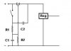
done with a small SCR.
I have drawn up this possibility for your consideration.
It is untried, by me anyway, so i cannot even suggest
values, other than describing their function as i see it.
The SCR in the diagram is the normal type where the gate
gets a positive to make the SCR conduct. I mention this
as there are other types about, but this is the most
usual in my experience.
Consider it first with the SCR conducting, if the button
is pressed, then C2 is placed across the SCR, and this
should cause it to stop conducting, however, the voltage
on C1 would be rising, and after a few seconds would
trigger the SCR back into conduction, where it would stay,
unless the user releases the button, and allows the
circuit to settle.
So the user would have to press then release within maybe
two or three seconds to switch off.
Consider it now with the SCR not conducting, if the button
is pressed, nothing will happen for maybe two or three
seconds, except the small pulse from C2 going to the
output, then the gate will reach the trigger point and the
SCR will fire.
So the user would have to press the button for two or
three seconds to switch on.
This arrangement might appeal because it is all-electronic
but the off state has the leakage of the SCR, which is
very small, and it means that a spike could turn it on.
Unlikely but it has to be mentioned.
Values ....
I would start with C2, by trying various capacitors across
the SCR to see what minimum value would reliably turn it
off. My guess would be about 3 MFD.
R1 ... this has to be as high a value that would turn the
SCR on, reliably, at the lower supply voltage, again try
a few resistors. My guess would be about 3K or 4K ohms.
C1 ... this has to delay the rising voltage on the gate to
give two or three seconds before the SCR fires. Difficult
to guess, maybe 20 MFD.
R2 ... this was added as an afterthought, it is to be as
high a value that will make sure that C1 is emptied
reasonably quickly when the SCR is in the on state, after
the button is released. Depends on the other values, maybe
20k ohms, or a bit less.
I hope these suggestions are of interest to you.
Any comments or points from any other members would be
welcomed.
Best of luck with it,
John
I am still tormented by the feeling that this can be
done with a small SCR.
I have drawn up this possibility for your consideration.
It is untried, by me anyway, so i cannot even suggest
values, other than describing their function as i see it.
The SCR in the diagram is the normal type where the gate
gets a positive to make the SCR conduct. I mention this
as there are other types about, but this is the most
usual in my experience.
Consider it first with the SCR conducting, if the button
is pressed, then C2 is placed across the SCR, and this
should cause it to stop conducting, however, the voltage
on C1 would be rising, and after a few seconds would
trigger the SCR back into conduction, where it would stay,
unless the user releases the button, and allows the
circuit to settle.
So the user would have to press then release within maybe
two or three seconds to switch off.
Consider it now with the SCR not conducting, if the button
is pressed, nothing will happen for maybe two or three
seconds, except the small pulse from C2 going to the
output, then the gate will reach the trigger point and the
SCR will fire.
So the user would have to press the button for two or
three seconds to switch on.
This arrangement might appeal because it is all-electronic
but the off state has the leakage of the SCR, which is
very small, and it means that a spike could turn it on.
Unlikely but it has to be mentioned.
Values ....
I would start with C2, by trying various capacitors across
the SCR to see what minimum value would reliably turn it
off. My guess would be about 3 MFD.
R1 ... this has to be as high a value that would turn the
SCR on, reliably, at the lower supply voltage, again try
a few resistors. My guess would be about 3K or 4K ohms.
C1 ... this has to delay the rising voltage on the gate to
give two or three seconds before the SCR fires. Difficult
to guess, maybe 20 MFD.
R2 ... this was added as an afterthought, it is to be as
high a value that will make sure that C1 is emptied
reasonably quickly when the SCR is in the on state, after
the button is released. Depends on the other values, maybe
20k ohms, or a bit less.
I hope these suggestions are of interest to you.
Any comments or points from any other members would be
welcomed.
Best of luck with it,
John