Continue to Site

Welcome to our site!

Electro Tech is an online community (with over 170,000 members) who enjoy talking about and building electronic circuits, projects and gadgets. To participate you need to register. Registration is free. Click here to register now.

  • Welcome to our site! Electro Tech is an online community (with over 170,000 members) who enjoy talking about and building electronic circuits, projects and gadgets. To participate you need to register. Registration is free. Click here to register now.

Biger coilgun (In development)

Status
Not open for further replies.

Someone Electro

New Member
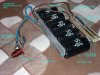
I just got some big caps. 2200uF 400V and 5 of them.They can realy pack a punch since this is 880J all togeter.

To switch this i need a big SCR or a lot of them.I orderd 10 of 25A SCRs wich should be enugh.Im still waiting for my order.

Il post here how i get along.

Oh and i know i should put on a bus bar(Wich i probobly will) and that the photo is prety much crapy.
 

Attachments

  • dcp01943.jpg
    173 KB · Views: 614
From bolha.com ,its a slovenian e-bay like site but much smaller.

Oh and you prbobly mean a can crusher.For this these caps a not good.You need those kilovolt caps to make a high enugh pulse.

The guys are waiting for somthing that is out of stock.So probobly no SCRs until next weakend. :cry: I only have 3 SCRs at home and those would certanly get fryed.
 
Woho!!! :D
My order was shiped out today.So i should get it tomorow.

Perfect timimg il get it right before weakend so i have plenty of time to work on it
 
I will cost me less to get many smaller ones and parallel them then buying a single huge one.

Each of these SCRs can take a non repitive 1ms pulse at about 250A,So 10 of them will do the trick.

Oh and looks like hte didnt ship the stuff out in the morning becuse i didnt get them yet.Hope they will deliver it tomorow.

I should get going on the cap voltage meshurment.So it will auto shut off charging when full.This will require triaks and foling whith mains.Wich is not a very good idea becuse i have no isolation transformer.
 
FINALY!!!!! :?

SCRs are here!!!

Ok now i need to make a bus bar to munt them on.

Il get to doing that tomorow.
 
I was thinkering whith the charger.First idea was to have it isolated from the mains.I dont have a isolation transformer so i tryed making out out of two transfromers.The charge times ware way to long.

Now i have decided to scrap isolation.Im gona have a reley switching the hot wire.Then have a ciruit to meshure voltage and control the reley.But after some more thinking i came up whith a way to make it even safer.When fired the charger should start charging agen to prevent this im gona add a charge start button.Im thinking off a flip flop wich has its reset tyed to the "charge complete" LED and thurn on to the charge button.So the reley is holded in the off state until i press the start charge button.

This is becuse when charging nothing is safe to toch.Becuse of a voltage dubler not even the neagtive rail.

Im also going to add isolation to the SCRs (Opto-isolators probobly) to prevent the control circutry going live when charging.

It is the most complicated mains cap charger ever.It may sound amost stupid whith all the safety precausons but i dont want anything bad to hapend.

I would use a triac if i had a triac driver IC.(Solid state is always better)
 
It sounds like it is very dangerous to have high voltage with a high current capability.
 
Whithout a isolation transformer i cant isolate it from the ground.So i minimising the live time.Im thinking of a 3 second charge time.

When the reley disconects the live wire then anything is safe to toch as long as you dont toch one wire at a time(And that only in the cap bank and SCR part)

Im also giving the circuit a dual suply.One powers the charger wich goes live when charging(Becuse of the voltage divider on the op amp)And one is the fire switch wich is completly isolated by a transformer and a optocopler.This rail will also power any cirucitry that i may add like remote trigering and stuf like that.

It would also be a good idea co cover the cap banks bus bar.A metal object falling on it would be a nasty suprise.

I have the schematic drawn on paper.

The op amp works good on the single suply altrough its not ment to work that way.I also added 2 diodes over the caps in the volateg dubler becuse i found out that at high load(empty cap bank is a short) the caps gets reverse charged and that spells bad for electrolics those diodes prevent that.

Is there a way to drive a triac whith a opto isolator or somthing?
 
Hi,
for safety your relay MUST be double pole and switch BOTH the Live (hot) and Neutral (cold) connections to the mains.
This is because the neutral is connected to ground (at the substation or transformer) so if you don't break it you can still get a circuit from the capacitor +ve through YOU to ground, back up the neutral and rectifier to capacitor -ve.
The relay should not close automatically, even if it releases automatically before you discharge. You should have to make a positive action such as pressing a button (preferably with a guard or two buttons in series. This also looks cool) and a warning light would be a good idea. Don't forget discharge resistors across the capacitor bank. I'd suggest one 100K 2.5W resistor across each capacitor. They should be rated for at least 350V. Even with these fitted it will take at least 5 minutes for the voltage to drop to a safe level.
Apart from your buss bar cover, be aware that the capacitors can expell hot gas and corrosive liquid from the safety vents near the terminals, or even EXPLODE in the case of a failure! they should be bolted down with the studs on the end and your buss bar shield should be arranged to catch the contents or direct them in a safe direction. Don't build it into an airtight box
Allways unplug the mains and chck the voltage across the capacitors before working on the circuit.
 
I did the bus bar and found some nice thick wire(about 4mm)So i now have the caps on a aluminium bus bar.

But there is a problem i found some coper that is in cm wide sheets i put them on a woden plank and wired it up then tryed to solder SCRs to it and solder dosent stick to it at all!I tryed scraching it a lot but it did almost nothing. It certanly looks like coper whith its prety orange shine.Looks like il have to get somtihng else.Il probobly get some of that fat wire,strip it and solder diertcly on it.
 
Someone Electro said:
I did the bus bar and found some nice thick wire(about 4mm)So i now have the caps on a aluminium bus bar.

But there is a problem i found some coper that is in cm wide sheets i put them on a woden plank and wired it up then tryed to solder SCRs to it and solder dosent stick to it at all!I tryed scraching it a lot but it did almost nothing. It certanly looks like coper whith its prety orange shine.Looks like il have to get somtihng else.Il probobly get some of that fat wire,strip it and solder diertcly on it.

If it's got a 'pretty orange shine' then, assuming it IS copper, it must have a protective layer - try rubbing it with some fine abrasive paper, and (if you've got it) rub some flux on it - then try and solder to it. I presume you've got a really large soldering iron?, otherwise the copper will conduct the heat away too fast.
 
No im using a small electronics soldering iron.But i can get my hands on a 100W one.

Il try the sand paper tomorow and see if i can get it solderd.
 
Someone Electro said:
No im using a small electronics soldering iron.But i can get my hands on a 100W one.

That's the sort of thing you need to be looking at for the copper strip, it's too efficient a heat conductor for a small iron.

I've got a nice 100W Weller iron at work, makes short work of big jobs :lol:

I wish I'd bought some more of them, a company we deal with was selling them off for £5 each - and I only bought one :cry:
 
I got a big 160W one and man this thing is powerful,not to menthon how clumsy the huge tip is :? .But after some mesing around i got it solderd i then fixed it a bit whith the small one(Wich luculy has a 10 times smaller tip )

I did the first test fire at 4% power.The caps charged to 60V or 40J and it was sucsesful.It got like half a cm in some styrofoam.Tomorow comes the opto isolated trigering for safety and a shot at full power.I hope the coil has a good enugh contact on that bolt that holds it to the fat wire.
 
Here we have the photo.

The snuber diode was the "last minte fix" I was screwing the coil on and then i toght "Wait a minute where do i have the diode to stop the kickback?"Then just quicky solderd it on
 

Attachments

  • dcp01948a.jpg
    dcp01948a.jpg
    168.6 KB · Views: 284
The first 100% Power fire was done. It was fired at styrofoam.The whole lenth of the nail got in it :shock: (Then comes the problem of getting the nail back out)

I toght theat it will go right trough becuse a shot at 300V left about a cm of the nail out and its prety hard to pull it back out styrofoam realy has a lot of traction betwen metal.Also the nail gets warm and coil much warmer(3 full power shots would probobly make it to hot to toch)

I certanly DO NOT want to get hit by that thing.

Projetile is a 7cm long and 4mm diameter nail
 
Status
Not open for further replies.

Latest threads

New Articles From Microcontroller Tips

Back
Top