Electro Tech is an online community (with over 170,000 members) who enjoy talking about and building electronic circuits, projects and gadgets. To participate you need to register. Registration is free. Click here to register now.
Welcome to our site! Electro Tech is an online community (with over 170,000 members) who enjoy talking about and building electronic circuits, projects and gadgets. To participate you need to register. Registration is free. Click here to register now.
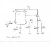
The amplifier circuit with negative feedback will try to keep the output DC output voltage at the same voltage as the input which is 0V.
Then the 10k load resistor has a current of 5V/10k= 0.5mA.
A tiny amount of current (only 2uA?) is the base current of Q2 which can be ignored.
Then the emitter current of Q5 is 2.5mA plus its small amount of base current (maybe 20uA) plus the 2uA.
Sorry, I didn't notice that R1 connects to -5V instead of to 0V. Then the negative feedback through R2 will make the output voltage as high as is possible which is about +1.4V. Then the emitter current of Q5 is about 2.75mA.
sorry but i cant see the point. feedback wants to keep output equal to input ok .. but there are 2 inputs here..we set them 0 for dc then I m confused :S ..May u explain with math process, please?
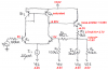
The input at the left side is connected to 0V through the 100k input resistor and signal generator.
The input at the right side has a 100k resistor to -5V (-50uA) so the output into the 1M negative feedback resistor R2 will try to go to 50uA x 1M= +50V.
The output cannot go to +50V so it goes as high as it can which is about +2.7V.
This site uses cookies to help personalise content, tailor your experience and to keep you logged in if you register.
By continuing to use this site, you are consenting to our use of cookies.

")