Electro Tech is an online community (with over 170,000 members) who enjoy talking about and building electronic circuits, projects and gadgets. To participate you need to register. Registration is free. Click here to register now.
Welcome to our site! Electro Tech is an online community (with over 170,000 members) who enjoy talking about and building electronic circuits, projects and gadgets. To participate you need to register. Registration is free. Click here to register now.
The pinout for the LM393 can be found on the datasheet which can be found using your favourite search engine.
Just connect the inputs of the unused comparator to opposite power supply rails, i.e. the + input to +V and the - input to 0V or the other way round, it doesn't matter.
EDIT:
Just another thing: it won't help here but you should be able to parallel the outputs of both of the comparators on the LM393, as long as they're on the same IC, the current sharing should be near perfect. This will help though, if you need to drive a large load with the driver transistor so you need to ensure a high base current in order for it to saturate properly.
You need to connect the power supply pins to +V and 0V, pin 8 and 4.
The only other pins which need connecting to the power supply are the inputs for the unused comparator, i.e. either pin 3 and 2 or pin 5 and 6, depending on which comparator you're using.
You've connected up both inputs to the power supply and left the power supply pins unconnected which isn't good.
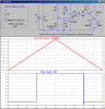
Hero's circuit still needs some tweaks. You will have a hard time finding a 9V relay. Common relay coil voltages are either 5, 6 or 12V. His circuit has way too much hysterisis. Use 1meg as the feedback resistor. Look at the attached sim. Note that with the 1meg feedback resistor, the circuit trips at 9.9K and 10.1K. With the 100K feedback resistor, the trip points are 10.9K and 9.1K, respectively.
Oh damn, i must admit i am struggling with this, i realise for a rank novice this is a tall order and a learning
curve, but i cannot afford the £100 plus price for the commercial version for my project.
i will have a go at the circuit with my breadboard still stuck with the transistor in the diagram, i do really
appreciate the feedback and comments given, i am happy to consider any alternative including different
power DC voltages (nice to keep easy ie AAA's or AA's or 9 v PP3 etc)
am also happy to consider low voltage relays (reed switch i believe at work so cannot get access to my
paperwork at present)
It is frightening how much i could pay for effectivly the same item bundled in a box with a posh makers badge, and pretty finish etc.
it is also a good thing to know that if i made it and a problem arises i have a good idea on how to fix etc, or at least where to start, and save another packet of money on repair costs (smiling to myself as i type)
This site uses cookies to help personalise content, tailor your experience and to keep you logged in if you register.
By continuing to use this site, you are consenting to our use of cookies.