Continue to Site

Welcome to our site!

Electro Tech is an online community (with over 170,000 members) who enjoy talking about and building electronic circuits, projects and gadgets. To participate you need to register. Registration is free. Click here to register now.

  • Welcome to our site! Electro Tech is an online community (with over 170,000 members) who enjoy talking about and building electronic circuits, projects and gadgets. To participate you need to register. Registration is free. Click here to register now.

Beerpong cup detector

Status
Not open for further replies.
If a driver can be managed that would be awesome. Once my 12v supply comes soon I can mess around with higher voltages and see how it goes. I think the higher base voltage and higher resistor seems to be the last chance. The voltage spat out by the cap during discharge is identical to what it was charged with, correct? With the el-cheapo multimeter I'm about to get shipped I doubt I can figure that out at time of discharge ;)

I may have to abandon the fade idea for the cups though if I really do need much bigger caps...40 of these caps are going to already be really costly so I really hope this will work. When choosing a voltage, since I'm working with 12v, is it safe to use 16V caps or is that cutting it too close? I hear that I'm supposed to use caps rated double the base voltage I'm using but this project needs to be as budget as possible lol.

this is getting dang complicated for a fade >.<

Reed switches are being triggered with magnet backed cups birdman.
 
Last edited:
Well I have an updated schematic, works now, but same problems with the fade:

**broken link removed**

The curious thing is, 100uf caps work FINE if hooked up in the junction between r3/r5 and respective LED chains. Unfortunately it will only fade the right side of the circuit...can the the principle that's happening here be used to create slower fades with smaller caps? I assume what is happening here is the solution you have, driving the LED's with transistors.

If I just hook transistors directly in parallel with the LED arrays, is it safe to use a 16v rated transistor?
 
Last edited:
Yeah-- the way the ckt works is such that it would only fade that one side... am a bit sleep deprived so "I'm trying to think but nothin' happens" ... If we could revise the circuit so as to put a 2nd cap in parallel with Q2 -- won't work right tho... need to think it over a little...
 
100uf caps work FINE if hooked up in the junction between r3/r5 and respective LED chains. Unfortunately it will only fade the right side of the circuit...can the the principle that's happening here be used to create slower fades with smaller caps? I assume what is happening here is the solution you have, driving the LED's with transistors.

If I just hook transistors directly in parallel with the LED arrays, is it safe to use a 16v rated transistor?

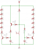
Quick explanation of the circuit... the transistors act as switches. They allow current to run through them. These are called Bipolar Junction Transistors or BJTs. That simply means there are two junctions fused together.

The line with the arrowhead is an "emitter" the line above that is a "collector" (connected to the LEDs/resistors). The line coming in on the side (with the 10k resistor) is a "base". When you send current into the base, then current can flow from collector to emitter -- at least in this case. These are NPN transistors. Current would flow the opposite way if they were PNP (the arrowhead would be pointing in instead of out, and would be at the top instead of the bottom).

So the transistor on the right (Q3) is easy to figure out. The reed switch is normally open so current flows from the source to its base. This turns it "on" and lets current flow thru that set of LEDS.

Q1 on the left serves the same purpose of turning on the LEDs on the left, but when S1 is open, current flows to the base of Q2 which turns it on, and bleeds current and voltage away from the base of Q1 so it is normally off.

When S1 closes, this grounds out the base of Q3 turning of the transistor and consequently the LEDs. Meanwhile it also turns off Q2, meaning full voltage and current goes into the base of Q1 turning on the transistor and consequently turning on the left bank of LEDs.

It's the Q1/Q2 part that confounds me as far as putting a capacitor in there...

Maybe there's another way to use transistors to turn the leds on/off from the single switch...

Anyway if we put the cap from base to ground, methinks this would allow us to use smaller caps for the same effect. Because transistors aren't just on/off. Current flowing into the base is something like 50-100 times less than that flowing into the collector. So 'fading out' the base current also fades out the collector current. This is the basis of transistor amplification, btw.

Michael
 
Very simple solution (also cost effective if I can work out the kinks):
**broken link removed**

Problem is, both the red LED's and R2 run VERY hot...
 
Last edited:
Hm... how about this??

ledfader3-png.30251


I'm not a super guru with the transistors so there may be some issues...

But the idea is that the PNP gets turned on only when the switch is closed, which in turn shuts down the right side transistor and leds; the diode prevents the right side cap discharging anywhere but thru the base of that right transistor. The left side transistor is turned on by the PNP and when it shuts down the cap drains fading the left side LEDs. Like I always say "it should work" :D
 

Attachments

  • ledfader3.png
    ledfader3.png
    8.5 KB · Views: 280
Last edited:
Alright, before I order some parts, the LED calculator I was looking at suggested 1/2watt resistors. How is this calculated and what will happen if I go with 1/4 watt?
 
You can figure out wattage (power). It is given by P = I*V where I is current and V is voltage. *or* since V = I*R then P = I^2 * R

So say you have 20mA thru all the LEDs and a 56Ω resistor inline, you get P = .0004 * 56 = 22.4mW. I can't imagine why you'd need a 1/2W resistor for such a small power dissipation.

I've been trying to learn SPICE so I can model the circuit I posted to see if it'll work right or not... haven't had much luck yet. :) So I don't know for certain if it'll work. If it were me I'd prototype parts of it at a time then put it together at the end and test.

Michael
 
Status
Not open for further replies.

New Articles From Microcontroller Tips

Back
Top