Continue to Site

Welcome to our site!

Electro Tech is an online community (with over 170,000 members) who enjoy talking about and building electronic circuits, projects and gadgets. To participate you need to register. Registration is free. Click here to register now.

  • Welcome to our site! Electro Tech is an online community (with over 170,000 members) who enjoy talking about and building electronic circuits, projects and gadgets. To participate you need to register. Registration is free. Click here to register now.

Battery-like Regulator?

Status
Not open for further replies.

ssashton

New Member
Hi guys,

I am trying to make a bluetooth audio module (based on CSR8645) run on a power supply. It has an input for +5V and draws about 60mA. Running it like this from a 7805 regulator produces a fair amount of high frequency switching type noise on the output though.

The module also has a connection for a 3.7V li-po battery so it can be used in portable devices. If I connect a battery on here, at the same time as the main power supply, the noise reduces significantly.

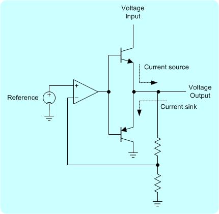
I guess the integrated battery charger circuit on the bluetooth device is 'looking' for a battery and putting out noise unless I connect one. My thought is that perhaps I need to build a regulator that can sink as well as source current and connect that in place of the battery. What do you think?

Can I just use a LM336Z5 (Fairchild) sunt reference with an adjust resistor to get a 3.7V output that can also sink current like a battery?

Thanks!
 
Last edited:
Do you have a 100nf to ground on the i/p, and a 1uF on the o/p of the 7805?, if not try it and see hat happens, linear regs can oscillate with long lines.

PS welcome to the forum.
 
Hi thanks for the reply. Yes I do, the reg is properly implemented and also not on long leads. The problem appears to be noise on the ground line.

Ive tried many grounding arrangements with small changes observed but not significant. Attach battery on the battery terminals at the same time as the main power supply and noise drops more than 20dB.

If it helps here is what I managed to trace from the Bluetooth module PCB. You can see the main power in goes to a 3.3v regulator while the battery connect on the other aide of that to the Bluetooth IC.

**broken link removed**
 
I Don't know Why you should have any High Frequency Noise from a 7805.
It is a Linear Regulator, so there is No High Frequency Switching.

You might consider putting a 10uF Tantalum Capacitor on both the Input and Output of the 7805.
 
Its not the regulator making noise its the Bluetooth module. I think it is the battery charger in the module. So to fool it into thinking there is a battery I need a power source that can both supply and sink current.
 
Thank you I'll have a careful read of that later.

I was hoping someone might have an existing design I can easily copy? Such as this one, but with the extra bits added in (the site I found it on said it is simplified).

wpe207aa60_05_06.jpg
 
A Battery happens to have lower ESR flat over wide bandwidth,m while any closed loop amplifier including the 7805 has low ESR at DC but rises with f.
So most likely it is the ESR of the regulator at fault which might be possible to suppress with a film cap with 10m Ohm ESR of suitable size or double layer electrolytic..

BT and WiFI TX draw alot of current in pulses, if you calculate the dv/di =ESR of the load and the ESR of source the ratio is your ripple.

Just ignore the capacitance and voltage and focus on the ESR or ESL of each component then ripple is just Ohm's Law as a voltage divider.
 
So basically you think my regulator needs a lower output impedance? I could try a 317 with a voltage reference IC on the adjust pin.
 
I dont think that'll make much diffrence, the o/p imp of the lm317 probably wont be a lot diffrent from the 7805, its a similar device just adjustable.
If impedance is the issue then as mentioned a tantalum cap across the reg is a good start, or pinch pull a low esr cap out of a dead smps and stick that onthe o/p, a good cap on the o/p of the reg will signifcantly lower its ac impedance.
 
The storage time constant x10 is the factor with ESR + ESR on source relative to load. Or peak current x ESR on source and allowed ripple after Cap discharges. LDO's Zo rises with f and Cap Z drops with f but ESR is fixed and LDO must meet your Vo min load requirements during peak current. And 10% SoC on Vbat

If you insist on an LDO use the 78R0x series 0.5V drop at rated I if sufficient for stall current.
 
For the most efficent solution consider **broken link removed** but may be over budget.
 
i remember a famous now defunct PC maker when I bought 2 identical PC's for my brother and his son. One PSU failed to boot as soon as Wifi card started to transmit and it had ample power. Source ESR and regulation issues on pulsed 2W loads with relatively low ESR Caps on load card . I swapped PSU units and it worked. Same company also had big recalls due to fires,, again ESR source issues. cap ESR ratios must be lower on source unless soft start used.

A small LiPo battery can be like 2000 Farads and 10mOhm ESR which lowers when hot and rises rapidly when discharged .

All power sources and loads after school have ESR which determines "Load regulation"
 
Last edited:
Thanks for all the information!!

I have tried putting a 22uf electrolytic and 100nF X7R ceramic in parallel on the output of the regulator which I think should lower ESR at high frequencies but it doesn't make a jot of difference.

I also tried a 317 regulator with a pair of LEDs on the adjust pin which gives significantly lower output impedance than the usual resistive divider. No difference. My friend wrote an article on using the LM317 like this, it is very worthwile reading - http://www.acoustica.org.uk/t/3pin_reg_notes1.html

Perhaps the problem is not just my regulator. My power supply is actually a little unusual because it is taking the +36V output from a laptop style SMPS and splitting it to +/-18V dual rail. This feeds an audio amplifier and crossover filter circuit which are dual rail devices. The 5V regulator feeding the bluetooth module then hangs off the +18V positive rail.

Here is my rail splitter design. You can see R6 and R7 which all DC must return through, so the supply DC output impedance is going to be 1R. However at AC frequencies current can return through the big smoothing capacitors. So I'm thinking the DC rail splitter will not be detrimental to high frequency pulsed current draw from the bluetooth module?

**broken link removed**
 
Last edited:
Sorry sshahton but your assumption is false.

If it is rated for A.rms at 100 or 120Hz it is better than Std electrolytic but low ESR spec parts are better and ultra low even better.

Do the test or look up specs for ESR for all components in source and switch load!!
 
Sorry I don't understand what you mean. Which assumption is false and what parts are you talking about rated at 120Hz?
 
Re-read why I have said about ESR and learn to read Cap datasheets for ESR and I max rating vs Caps with no specs. They are all different construction in quality, cost and performance.

Impedance drops with rising f but ESR is fixed... until ESL dominates at the midpoint of equal impedance you also have ESR at the Series Resonant Frequency. (SRF) sometimes called Self Res Freq as there is also a PRF for parallel Res Freq sometimes quoted but only by microwave parts.

which I think should lower ESR at high frequencies but it doesn't make a jot of difference.

I can back up everything I say.

Dont stop learning until you understand ESR cold. period. for all parts.

https://ultracad.com/mentor/esr and bypass caps.pdf
 
Last edited:
What you are saying basically is the 7805 regulator has too high output impedance at high frequencies and it needs suppressing with a low ESR cap across it's output? More precisely a cap with lower ESR than those on the bluetooth module.

I don't know exactly what caps are on the bluetooth module since they are tiny SMD parts. I have tried different caps on the 7805 regulator output and it makes no difference (tried tantalum 10uF, 100nF X7R, 22uF aluminium electrolytic, 1000uF electrolytic). There is a 3.3v regulator onboard the bluetooth module so perhaps this is where I should try the different caps?
 
If you dont know and dont read similar part datasheets and keep asking why you dont understand, you never will.

read the link I posted, then lookup the ESR specs in parts you need and pick a source ESR >10x smaller than the load.

Thn make sure the C value can support the RC time duration required if it exceeds the duration of the RF burst, but normally the regular must supply this burst level but not the cap charge surge. This is done by a 10x bigger cap with <10% of the ESR of the load for 20% ripple. THen if you need 5% ripple scale C and ESR according as you have both a C divider ratio and an ESR divider ratio.
 
I've been experimenting a little. Rather than putting different caps on the output of my regulator I tried putting them on the output of the regulator onboard of the bluetooth module. This has made a small difference. I've tried a 15uF tantalum and 1000uF Panasonic electrolytic (FR series with low ESR https://www.farnell.com/datasheets/1897635.pdf ) and the noise has reduce slightly. However it is only slight.

I have however found the solution! The problem is RF coupling to a small op-amp on the bluetooth module that buffers the audio output. This device is way too close to the antenna and a small amount of shielding aroudn the op-amp makes the noise disappear entirely. Woopy!

I can only guess this noise was being decoupled by the low ESR of the battery as has been suggested above, but no caps I've tried have done an equivalent job and the real solution is to shield the audio components.

I did think of this when I heard the noise at first but moving the bluetooth module nearer and further from my amp PCB made no difference so I went off in another direction. I didn't consider the problem was the output op-amp on the module PCB itself.
 
Status
Not open for further replies.

Latest threads

New Articles From Microcontroller Tips

Back
Top