Continue to Site

Welcome to our site!

Electro Tech is an online community (with over 170,000 members) who enjoy talking about and building electronic circuits, projects and gadgets. To participate you need to register. Registration is free. Click here to register now.

  • Welcome to our site! Electro Tech is an online community (with over 170,000 members) who enjoy talking about and building electronic circuits, projects and gadgets. To participate you need to register. Registration is free. Click here to register now.

Basic LED display project help needed

Status
Not open for further replies.

Dave001

Member
Hey new guys here, have an LED display project I need help with.

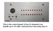
So I have a panel with rows of LEDs that correspond to each room, when a call is sent from a room the corresponding LED is illuminated.
I want to take the power going to the LED and instead have it light up a large 2 digit numeric display LED that will show which room number the call is coming from.

I only have basic soldering and electronics skills, so I want to keep it as simple as possible.
I would guess there is some kind of module/ chip that has a bunch of input channels (for each LED, 12 total) which when triggered with a input voltage would illuminate a programed number?...

Huge thanks in advance!!
 
How is the call turned off?

Mike.
The call button panel in the room has a "cancel" button, Which in turn shuts off the LED on the control panel. I see it being the best option to take the power going to the LED and divert it into being the input signal for displaying programmed digit on LED display.
 
Yes to both.


Regards, Dana,
Just blank.
It wouldn't... I though you wanted a "basic" system.... I would do it with a pic..
I agree, this is definitely suited to some form of processor.

Arduino (nano) is probably most suitable as there's lots of example code available.

Mike.

You all have a good idea for how to make this work. I appreciate all the feedback.
Now that I know there is several ways to do it, Would any of you be wanting to send me a quote on building this for me?
 
Can more than one LED be lit at once and if so, what does the cancel button do?

Mike.
Yes more than one can be lit at once. From what I can tell on the diagram, and from what I remember when I wired it up, there was 3 wires that I used. Both the call and cancel buttons are momentary push, so it does not hold a circuit. only sends a momentary signal to the control panel.
 
Heres some pics if that will help
 

Attachments

  • Screenshot 2022-10-12 22.05.35.png
    Screenshot 2022-10-12 22.05.35.png
    111.2 KB · Views: 185
  • Screenshot 2022-10-12 21.58.02.png
    Screenshot 2022-10-12 21.58.02.png
    352.2 KB · Views: 186
Everyone here was assuming that each room had a simple push button with wires back to the display panel. We now find out that each room has a "communication" device to inform the control panel what to display. That completely changes the ball game.

I'm still a little confused. Say five people in rooms press their button and (I assume) five LEDs light, you press the cancel button, what happens? Or, is there a cancel button in each room?

There are so many unanswered questions that it's impossible to come up with a design.

It may be possible to make a design that simply looks at the LEDs and displays a number but it would need a processor to remember the order that LEDs were lit so it can display the next priority number.

Mike.
Edit, Another problem is the LED display is probably a multiplexed display so the LEDs aren't constantly lit.
 
Last edited:
From a look at the makers other diagrams and info, each room alarm unit just switches it's "A" terminal to ground when triggered, so it's not using complex signalling in that part.

The LED panel is not much more than lamps commoned to V+ (12 or 24V) and each lit when it's individual terminal is externally grounded.
 
From a look at the makers other diagrams and info, each room alarm unit just switches it's "A" terminal to ground when triggered, so it's not using complex signalling in that part.
There's 5 wires go room to room, two of them are power. How do you signal 12 (or 20) events through three wires without some kind of complex signalling?

Mike.
 
There's 5 wires go room to room, two of them are power. How do you signal 12 (or 20) events through three wires without some kind of complex signalling?
It presumably does use digital signalling on that bus - but the annunciator panel with the LEDs does not connect to the bus wires.

It just has power, ground and the "A" wire from each unit, which is also used for an optional alarm indicator light for local alarm indication.

The LED panel shown in the diagram is only 10 way, showing "A" wires to the first two input. They make them in different sizes.
 
Ahh, I see what you're saying now, I think. The A wire travels from each of the rooms back to the annunciator panel.
I'm guessing the two modules (center bottom) must be in each room.
Not sure why 5 wires need to travel to each room (especially the P wire).
So, in the OPs case, a 12 LED unit, 5 wires go out and 12 wires return.
I'd still like to know how the cancel button works.

Mike.
 
Dave001, if you can explain how the cancel button works then it may be possible to design a circuit to do as you requested.

Mike.
 
Everyone here was assuming that each room had a simple push button with wires back to the display panel. We now find out that each room has a "communication" device to inform the control panel what to display. That completely changes the ball game.

I'm still a little confused. Say five people in rooms press their button and (I assume) five LEDs light, you press the cancel button, what happens? Or, is there a cancel button in each room?

There are so many unanswered questions that it's impossible to come up with a design.

It may be possible to make a design that simply looks at the LEDs and displays a number but it would need a processor to remember the order that LEDs were lit so it can display the next priority number.

Mike.
Edit, Another problem is the LED display is probably a multiplexed display so the LEDs aren't constantly lit.

Each room has a small panel that has only mechanical switches, no circuit boards. (only has a few resistors or something that keeps the "call placed" led on until the call is cancelled).
Has a momentary switch for placing a call, and a momentary switch for cancelling the call.

Cancelling the call at the room turns off the LED for that room and audible beep at the control panel

If there are other rooms that placed calls at the same time, the LEDs for that room will stay lit at the control panel until each room call is cancelled inside the room, and audible beep will stay on until all rooms are cancelled.
Screenshot 2022-10-12 22.04.45.png
 
Status
Not open for further replies.

Latest threads

New Articles From Microcontroller Tips

Back
Top