Continue to Site

Welcome to our site!

Electro Tech is an online community (with over 170,000 members) who enjoy talking about and building electronic circuits, projects and gadgets. To participate you need to register. Registration is free. Click here to register now.

  • Welcome to our site! Electro Tech is an online community (with over 170,000 members) who enjoy talking about and building electronic circuits, projects and gadgets. To participate you need to register. Registration is free. Click here to register now.

Automatic spoiler 'contest'

Status
Not open for further replies.

BibaResto

Member
Actually I prefer two people who Absolutely Know Without A Doubt they can make the spoiler, as found on Ltd. and Base Chrysler Crossfires, to work on my 2005 SRT6 Crossfire (XF). One of the persons is a programmer, the other knowledgeable in what electronics to utilize to make the program work. I prefer this to mount inside the spoiler if possible.

The amount I’ll pay for a complete functioning automatic spoiler is $500.00. If you can also utilize the original dash switch I’ll include another $100.00. The deadline for the completed/functional spoiler is no later than March 29, 2018.

The spoiler should automatically open at 62 mph and close at 42 mph. The SRT6 comes with an exterior non-movable wing. It can easily be removed and the working, automatic spoiler can be directly bolted in. Meaning no additional equipment/fasteners are needed to install the functional spoiler (and dash switch) I have - of course along with whatever ‘equipment’ you have ‘designed’.

I have included a number of comments in the past regarding the spoiler on this forum, so please check them out before asking any questions. There are also photos of the equipment and what little I know about the spoiler’s workings.

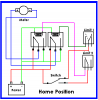
I do have the spoiler and switch and about a dozen generic switches - none of which will open and close the spoiler. I can make the spoiler open and close by switching the two wires on the motor.

I am illiterate in electronics. I will add, with no more than a toe in the water, I understand a lot can be done with varying voltages.

Go back to around May 2016 for the previous posts. I’m pretty sure this was the Forum.
 
I hope I'm not opening a can of worms here, but after skimming through that thread, it appears that it was never definitively stated that the motor is supposed to reverse, yet there was a lot of discussion about motor reversing circuits and switching. My own experience with an automotive actuator (pop up headlights in my case) is that the motor does not reverse. It simply operates a cam or a crankshaft. At 0° of cam/crank rotation, the device is retracted. At 180°, the device is extended. To retract the mechanism, power is simply re-applied, the motor rotates in the same direction until it hits 360° —the starting position— and then it stops. Limit switches are located at the 0° and 180° positions to stop the mechanism in the correct positions. The advantage of this type of mechanism is that a failed limit switch won't cause the mechanism to jam. If a limit switch fails then the device either doesn't run at all or else it continuously cycles (just like windshield wipers running continuously). Circuit operation is very simple. Either limit switch will stop the motor. To cause it to operate, you need only shunt one of the limit switches. It will move to the opposite position and the other limit switch will then stop it.
 
(I sure wish I didn't have to log in every time I visit).

BobW, trust me the very torquey motor starts out clockwise (depending on how you're viewing it) until the limit switch stops it. Then turns counterclockwise to lower the spoiler, again stopped by a separate limit switch. I assume the difference between your auto headlights is this arrangement has a small gear at the end of the motor which turns a much larger gear. This gear is attached to a longish rod, which turns gears at the ends opening and closing the levers attached to the spoiler.

My thinking to just get them to open and close was to follow diagrams for power windows. I'll add that I installed power windows in my Alfa Alfetta GT which came with wind up windows. As long as the battery is completely charged, they work quite well.

But jumping to what I feel might be the most difficult spoiler part is the opening and closing at specific speeds. I'm sure the speedometer can't and shouldn't be hacked. But is there a nifty electronic device which can be triggered using very specific voltages? If it had the means to physically turn the voltage up or down, it shouldn't take long to dial it in.
 
But is there a nifty electronic device which can be triggered using very specific voltages? If it had the means to physically turn the voltage up or down, it shouldn't take long to dial it in.

supper simple - comparator, and looks like people have already said that in your previous post. The OBD was also mentioned as a way to get the speed, which I think is a good idea.

To put your $500 in perspective, I've got some school students at the moment designing a spoiler (mechanics and motor drive) as a engineering in school project. The budget for this is £1000.
For your spoiler you could probably get all the parts in for under $500, particularly if you have the spoiler already, but you leave no pay for the engineers.
 
BobW, trust me the very torquey motor starts out clockwise (depending on how you're viewing it) until the limit switch stops it. Then turns counterclockwise to lower the spoiler, again stopped by a separate limit switch.
Okay, good. Just thought I should check.

As for a speed signal, I think every vehicle from the mid-1990's onward has a master speed signal that operates speedometer, the ABS and cruise control. That signal should be accessible without too much effort, and would be the logical choice.
 
(I wrote the following yesterday, but failed to email it).

JimB was kind enough to send me the URL of the past responses regarding the automatic rear spoiler.

https://www.electro-tech-online.com/threads/automatic-rear-spoiler-project.148193/

I’ll add that I’d stopped replying in 2016 because a two person team (programmer and electronics expert) emailed me saying they would take on the project. The estimate was $250 for everything. When I asked the programer if he was confident to do it, he replied that absolutely he/they could come up with what was needed.

I probably shot myself in the foot by only waiting a couple of weeks, brief reply, and a month later checked in. I received a letter from the programer saying he (not his term) said he had a lot on his plate so would have to bail on the project. I was disappointed since it was more-or-less a done deal. However I fully understood since at times I need to pass on an additional restoration project so as to concentrate on the ones in the shop.

***********
Misterbenn, thank you for the offer. While I didn't state it, my plan is to ship the spoiler to whoever has at least a semi-functioning program. It would then be used to test the ability to open and close the spoiler ulitizing the limit switches. The latter is most important since the round torquey motor is only attached with a cable tie. If the motor doesn’t stop automatically, the motor will continue turning which causes the contact to both bend and ground to metal.

Perhaps students in the UK are unlike those in the US who pay to attend classes. I’m not dismissing your offer, but feel the student project is akin to at least partially paying for their tuition along with enough money to cover any trial and error electronic adaptations. Should you have a sharp student or pair of students who can program and build a somewhat difficult device in their spare time by March 29, 2018, please have them contact me.

For now I’ll be keeping the figure at (US) $500.00.

Biba
 
BobW:

Take a look here: https://electromen.com/en/products/item/motor-controllers/dc-motor/EM-231/ I recently found this controller and it does have some of the safety aspects of a good design.

There is a CAN bus that has speed accessible under the hood.

The factory limit switches utilize a +5 V signal.

Operation of Overide:
The spoiler can also be deployed at lower speeds using
an override switch mounted in the center console.
Once manually deployed, the spoiler will only retract by
pressing the bottom of the spoiler switch. The spoiler will
then retract in steps as long as the switch is depressed. If
the switch is depressed until the spoiler is fully retracted,
a short beep will be heard, and automatic control will be
reestablished.

The spoiler manual: https://www.crossfire-garage.fr/doc...R SERVICE PARTS AND PROCEDURES 2004-10-05.pdf

Info gathered on the web suggests steps when extending. Excessive current when deploying causes it to retract to home.

A schematic is here: https://www.electro-tech-online.com/attachments/spoiler_schematic-jpg.102834/ There's another schematic (except SRT) which has a 200 ohm resistor for the switch, a high side driven diagnostic LED (unknown Vf), a high side Illumination LED (unknown Vf). Unknown voltage applied to switch, but I think it might be 5V. would need to extract the page. Attached as Alternate_Spoiler_Schematic.

If the controller (except SRT model) had a 200 ohm pull down resistor in it, then you would have 0V, 1/2 Vcc and Vcc as thresholds with 0V being OFF. Down = 2.5 V and Up ~ Vcc. It would also make 12.5 mA a good number for wetting current. Thresholds of 1/3 and 2/3 Vcc with three windows should work fine.

The wierd limit switch arrangement causes problems too. Based on the schematic only, the switches open when at a limit and are pulled to ground in between the limits. Not confirmed independently.

Even for a simple controller, the limit circuit designed wrong could cause the motor to briefly turn on at say every engine start.

We never got from Biba critical information:

1. The value of the internal switch resistor. There is apparently a LED in that switch too and possibly illumination. The switch on the (except SRT model) which i assume Biba has is wired differently. The spoiler switch MIGHT HAVE 6 terminals with 4 being active.

2. At least the operating motor current. Motor resistance is harder to get.
This https://www.pololu.com/product/2452 and a few xtra parts would help get a reading assuming < +- 15.5 A is probably a good max number. You need a 5 V supply. Possibly a cell phone USB adapter.

Life for me has gotten very crazy, now being a full time caregiver for a bed confined parent. I'd be willing to try to reverse engineer the switch for starters.

Mating connectors are another issue.

My concern seems to be the same as Biba's right now. Any overrun without motor protection is likely to do damage. That was and is my biggest concern. The automotive environment with power supply dips and swings is another.

Some order of magnitude current draw, I think, is essential to proceed. There's 40 extra lbs of downward force on the spoiler. That's a big number.

It's a really tough project. With typical professional labor rates at say $150.00/hr (I'll use an auto mechanic as an example), I don't think a design can be done in less than 4 hours.
 

Attachments

  • Alternate Crossfire Spoiler Schematic.pdf
    179.8 KB · Views: 153
(I wrote the following yesterday, but failed to email it).
Perhaps students in the UK are unlike those in the US who pay to attend classes. I’m not dismissing your offer, but feel the student project is akin to at least partially paying for their tuition along with enough money to cover any trial and error electronic adaptations. Should you have a sharp student or pair of students who can program and build a somewhat difficult device in their spare time by March 29, 2018, please have them contact me.
Biba

To clarify I wasn't offering my students just trying to explain that the price your listing may not be sufficient as in this thread you hadn't until just now explained that you have the spoiler and motor.

Misterbenn, thank you for the offer. While I didn't state it, my plan is to ship the spoiler to whoever has at least a semi-functioning program.
Biba
That won't guarantee a working system, without the car its not possible to check the CAN bus or other speed measurement signals are working correctly.

My thoughts on this, were I to do it, get an Inertial measurement unit (IMU) to calculate the speed, use an Arduino with a motor shield or beefy H-bridge (we don't know the current requirement yet) to drive the motor. This would then work as a separate unit with only a power connection to the car.
Or if not an IMU, maybe an air flow sensor.
 
here's https://www.sailesmarketing.com/shop/can-bus-interfaces/cb-2-can-bus-interface/ an interface with not a bad price that supports the Crossfire out of the box.

So, you can get Speed and RPM signals from the Crossfire. See https://www.soundlabsgroup.com.au/p/CANBUS-CB2/CANBUS+CB2+Speed+and+RPM+Interface for a price about $165.00 AUD or about $130.00 USD. for RPM and Speed.

Frequency: Approx. 1Hz per mph
Output voltage: 12V square wave
Minimum speed: 1.7mph
Approx. pulse/mile: 3600
Engine speed: 2 pulses per revolution

Would save a lot of work and the vehicle should not be needed.

You still need an Autoelectronics installer to install it and run wires to the trunk if this is the most likely spot for a controller and assuming the manufacturer wants it in the engine compartment.
 
This will get you speed for $14.53. Almost plug & play.

GPS Module with Ceramic Antenna for DIY Handheld Positioning System for $7.86
https://www.dx.com/p/open-smart-gps...ino-apm2-5-flight-control-480918#.WiDKElWnH4Y

This is the data, info & an Arduino sketch that works as is.
https://drive.google.com/drive/folders/0B6uNNXJ2z4CxVGtacFJiM1B6OTQ?usp=sharing

UNO R3 ATmega328P Development Board With Boot Loader For Arduino UNO $6.67
https://www.walmart.com/ip/UNO-R3-A...9984&wl11=online&wl12=846733793&wl13=&veh=sem

Just 3 pins / wires to solder.

This is the NEMA ascii sentence that it works with
$GPRMC,225446,A,4916.45,N,12311.12,W,000.5,054.7,191194,020.3,E*68
225446 Time of fix 22:54:46 UTC
A Navigation receiver warning A = OK, V = warning
4916.45,N Latitude 49 deg. 16.45 min North
12311.12,W Longitude 123 deg. 11.12 min West
000.5 Speed over ground, Knots
054.7 Course Made Good, True (heading)
191194 Date of fix 19 November 1994
020.3,E Magnetic variation 20.3 deg East
*68 mandatory checksum

The speed variable in knots is "lndSpeed". It is an ascii string.
After extracting the whole number you can make it an integer with this function: int value = my_string.toInt();

You can convert with 1 knot = 1.151 MPH or 62 MPH = 54 knots & 42 MPH = 36.5 knots.

After you tweak the program to do what you want, just use an Arduino relay shield to operate your motor.
 
Last edited:
I apologize for not checking in lately but I wasn't receiving these later ones. A. I'm perfectly fine if some of you to think 'out loud' via this forum. However don't remotely expect me to understand any of the information. B. Okay, I went to one of KeepItSimple's... sites and the voltage required was an immediate delete. C. While I won't give it an absolute no, I Much prefer any solution not be predicated on hacking or adding too to make your 'solution' work. D. For some reason Pintrest sends me stuff to look at. I believe one was an Arduino project. It was a motor with a fairly long round shaft - similar to the one in the XF spoiler, but I forget what it was supposed to do. I might be mixing Ardinuo with something else, but if correct it appears to be a plug and play system. I don't want a clunky solution since I frequently use my trunk. There's not even a spare tire since below the trunk is also packed. E. I am somewhat flexible dollar amount wise regarding a working solution - however I need proof you're able to complete the project and do so by 03/29/2018. D. This mess is a Directed 535T automatic window opener. Obviously I couldn't get it to work. My guess is that it needed to be connected to the car itself to work. There is (in theory) a switch could just be pushed and goes all the way up or all the way down. Obviously it would be a work around but I could live with it until a 'proper' a proper solution was found.
 
B. Okay, I went to one of KeepItSimple's... sites and the voltage required was an immediate delete.

Your probably referring to "current". We really need the "order of magnitude" value. It can determine the physical size of the box. How many amps does the motor draw when moving?

The switch: Apparently there are two different switches. One seems to an UP/Down with a resistor fitted, And one has UP/DOWN/Malfunction/Illumination fitted.
I would think the latter is for the fully automatic spoiler. The resistor is listed as 200 ohms for the latter and unknown for the former, but probably 200. Illumination may have to be worked out, but one can make the malfunction LED work without damage by not knowing if it's a 12 V LED or a 2.1 V LED, a 5 V LED with an internal or external resistor.

Protections: Motor, limit switch breaking and bodily harm (a body part getting stuck). That's part of the OEM controller's job. My understanding is the spoiler is safer in the up position. So, if it tries to retract and runs into resistance, it goes up and stays up (malfunction).

if it tries to go up, it goes up in stages, so if someone happens to be leaning on it, it moves a bit and stops, so that person gets out of the way. My understanding is it would return home and indicate a malfunction. SO, let's assume the operator is not a moron and just interface the limit switches for manual operation and you rely on only a fuse for overload protection. Let's further assume the bright operator won't jiggle the switch and would stop before changing direction. That can blow fuses.

There's the mention of a chime that dings when fully retracted manually, that Biba says doesn't exist.

I believe manual deploy may be a momentary push. which would go through the normal protections, but a brief pulse is all that's necessary.

I also get the impression that manual retract requires on the hold the switch until a chime is heard. If the switch is released, it goes back up,

I agree, I mixed up the terminology and didn't go back to fix it.

To re-cap:

MANUAL/AUTOMATIC: Really has safety (property, people, motor) as it's goal. Even auto-deploying > x mph and retracting <y mph is a safety issue (better control of the car when deployed at the proper speed) and probably better mileage when it isn't needed.

FULLY MANUAL: 1st goal is make the limit switches work. 2nd goal, make the OEM switch work. 3rd goal (may be unrealistic) Don't rely on a simple fuse for overload protection. 4th goal (possibly unrealistic) Playing with the switch won't blow a fuse.

CONCERNS: motor protection, property damage, people damage, (creep/erratic operation), connectors

Creep/Erratic operation: Reading on the Crossfire forums suggests that the sign of a bad battery is erratic spoiler operation. That you need to avoid. "Creep" is defined as the circuit somehow interprets the limit as valid in the wrong way and say advances the spoiler "more closed" when really it was not supposed to move. This could easily happen at "crank" if your not careful with the design.

Connectors: Are just an easy way to interface with the current gizmo. You can always parallel your own spliced connectors.

IMMEDIATE NEEDS:
1. Order of magnitude current draw?
2. What switch?

Totally unknowns:
How does illumination come into play? a) Full on; b) Dim with dash lights. c) Other
I have indicators in my car (brake, traction off and others) that don't dim with he dash lights. They are separate from illumination.

CAN bus: Assuming that bus is used, Someone competent has to do the actual splicing.

Video of the spoiler opening and closing: Would like one

Comments: The clothes washer has a lid switch. it's not fixed because it takes too long to disassemble and replace. I have the switch. Current switch is Ty wrapped so it will work. Real failure reason has been fixed: Deterioration and upgrade of the lid bumpers. I'm the only one using the washer. We can apply that same analogy to the spoiler.

I did see your public comments on the EE/programmer that offered to help.
 
Last edited:
# 1. The last thing the spoiler needs is a nanny. If I hear one more word about incorporating a 'motor protection' in the mix, I'll skip right by the post. For god's sake, Mercedes/Chrysler had no provision of someone running up and sticking their hand in between the spoiler and trunk if the spoiler is closed manually. However, they do have the spoiler - at around 40 mph - close, not for security, but the spoiler is simply not needed at lower speeds. Now, go back and read the initial post. After the portion about getting the spoiler to go up/down automatically I'll pay $500. Should the original switch be used, I'll pay an additional $100. Meaning it is relatively unimportant.

The person/persons who understand what is needed will most likely concentrate, on the main parameters of the project - and might well not care to fiddle with the original switch. In any event, the solution also has to take into consideration there are five wires which need to find a home. I assume a printed (not printed?) circuit board will be used. With one 12V and one ground going in, it will need to have two separate 12V(?) for the motor and the other for the limit switch 12V(?). The limit switches also need the second ground. Admittedly what little I've run across, which makes sense to me are notations of using say an 8.3V to trigger a specific action. The original switch - and I'm just using this as a separate notation, is the voltage requires 5V.

Perhaps I'm way off, but if anyone here has knowledge of using various voltages - not exceeding 12V - to trigger a particular action/actions, please speak up.

I somewhat apologize for being so adamant, but I know what I want and get frustrated when someone decides on a particular need - which to me it definitely isn't.
 
For god's sake, Mercedes/Chrysler had no provision of someone running up and sticking their hand in between the spoiler and trunk if the spoiler is closed manually.

From:

https://www.crossfire-garage.fr/documentation/technique/US-UK/Technical_Service_Bulletins_-_TSB/2004/23-040-04 REAR SPOILER SERVICE PARTS AND PROCEDURES 2004-10-05.pdf

To prevent injury, the rear spoiler retracts in defined
steps to allow time to pull any hands or foreign objects
that may be in the path of the rear spoiler before it is all
the way down.


Second, from the same source:

If the rear spoiler gets disturbed while
retracting automatically or while retracting manually,
the rear spoiler is automatically driven up again and will
lock in the up position

disturbed is sensed by the motor current. Torque is proportional; to current.

BTW: A hand is a people part.
 
Last edited:
Tell me when will a hand be able to stick it in the spoiler when it is closing? Opens at 62 mph closes at 40 mph. If one opens or closes it by hand no one in their right mind would do so with people around. Very few times it makes sense to open it by the switch. In any case there will be no nanny. Period.
 
Agreed. It's not that important unless a limit switch fails. Like I had said somewhere else. The car is made for other climates other than California. Ice from freezing rain for instance, can likely freeze a spoiler shut. So, now it tries to open automatically and can't and let's face it it seems easy to find a stupid person. Someone leaning on the car at rest. In an accident and a tree falls before the spoiler can retract. I know, hypothetical issues. New washers/dryers won't even let
you open the lid at all,

A. So, which switch do you have? The manual one or the fully automatic one? How does illumination of that switch work on the fully automatic Crossfire in terms of illumination?

B. Can you get an idea of the current draw unloaded? At least something close. Unloaded means at 0 mph. Current at 62 mph would be helpful too. That's where there is downward force of 40 lbs on the spoiler or rig a 40 lb weight on it. Those two numbers would be ideal. e.g. Take off the spoiler part and rig a plywood platform/box that weighs 40 lbs and measure the current?

C. Have you tried to obtain mating connectors?

It's cold in February on the East coast where I am, I know the spoiler mechanism is not that big without the actual spoiler.

I tend to look at all possibilities, but not act on all of them. It's just me. That's how stuff lasted 17 or more years at work and the stuff was able to be repurposed. I provided support in a basic research environment including engineering.

At home, I'm constantly fixing stuff in a manner where it won't break again. This instant, I'm fixing deficiencies in a Lane leather recliner which is close to 40 years old. It's not supposed to last that long. When you reverse engineer stuff, you find places that have issues and you fix these. I just miss a machine shop. Membership is a close by Makerspace is tempting, so is fighting for $10/hr machine shop time elsewhere which I should be entitled to. The effort required will be huge, unfortunately.
 
Question already answered in the other thread.
 
Last edited:
For now, I'm putting the Automatic portion of this thread on hold (unless someone feels they are capable of designing and producing a working 'unit'). Today after looking at a no brainer switch diagram I thought Id give it a try. Easy, piesy. After wiring it up and as luck would have it I pushed the double pole double throw switch and the spoiler went up. Pushed the other side and it went down. How I've missed this in the past is beyond me.

I've had a copy of this diagram below and tried it in the past, but couldn't make it work. Okay, a ($50 if you use Paypal; $25 if I have to send a check) for someone to read through this article - RobMyerProductions/bows.html. Even if you have in the past please make another run through. What I need is verification of the following:

I had both SPDT relays wired the same - from the top 85 86 / bottom 87A 30 87 - correct?
A diode needs to be wired in - what would you suggest for the diode (be specific & color of the colored stripes would be nice). Where are they wired in specifically - meaning not a name, but a location for both ends?
Switch - is a single pole single throw or double pole double throw? I'm guessing a single pole single throw since that's the only switch I don't have.
Screen Shot 2017-12-07 at 6.32.29 PM.png
 
Status
Not open for further replies.

Latest threads

New Articles From Microcontroller Tips

Back
Top