Hello guys.
I'm getting married in a little bit over a month. Since it's a small reception (less than 30 people) we're doing most of the decorations and a lot of other stuff ourselves to save some money. Long story short we are renting an automatic bartender since it's three times cheaper than an actual one and I got an idea for a sound emitting decoration inspired by BioShock PC game vending machines, that plays a sound whenever someone approaches to use the machine and get a drink.
I got inspired by a couple of youtube videos and got a 5V one channel relay module, a PIR HC-SR501 motion sensor and a DFPlayer Mini (MP3-TF-16P clone to be exact). It turns out it's a bit more complicated when it comes to a DFPlayer Mini without using a microcontroller like an arduino board (I don't know anything about code writing and the required components are significantly more expensive). I couldn't get it to work properly with just a relay module but after some online research I at least figured out what is the issue so I'm hoping you can help me solve it.
What I've done so far:
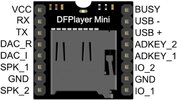
I connected 5V battery pack power supply to VCC and left side GND (players pinout attached) and a speaker to SPK_1 and SPK_2. Simplest way to play one song is to a connect an output wire from the PIR sensor (of course wiring it to power supply first) to a relay module (https://bit.ly/3SvZhpP) and connect COM to right GND and NO (Normally Open) to one of the function keys on a player (IO_1, IO_2, ADKEY_1, ADKEY_2). The ADKEY functions require various resistors to choose a certain function. To make things as simple as possible you can either use ADKEY_1 without any additional components to play song number one, which is what i tried first, but it turns out once activated the player plays the song over and over. PIR sensor's signal is just interrupting the playback and making the song start over, but the player never powers down. Second way is to use either IO_1 or IO_2 (next/previous song) because when the player is powered down it just plays the first song no matter which one of those two you activate and then powers down, which is all I need for my application, but here's where we get to the main issue:
When you connect a push button to the right side GND and IO_1 or IO_2 it serves two functions: when it's pushed briefly it starts playing the first song but when it's held down it changes volume up or down. That's what I was accomplishing with a relay module, the player just kept changing the volume instead of playing the song.
To sum it up I need a way to simulate a brief pushing of a button using a PIR sensor's signal. The relay module closes the circuit for far to long and the player just changes volume. I need something simple to make a pulse-like momentary connection between the right side GND pin and IO_1 or IO_2 so that the player plays a song when there is motion detected and then powers down. I tried finding a solution and i stumbled upon positive edge triggered d-type flip flops, since the PIR sensor sends HIGH output when it detects motion and has a wide range of delaying and otherwise easily regulating how it reacts to movement. Someone suggested this type of flip flop and using it to emit a positive 5V pulse whenever a rising edge is detected by connecting 5V to the Data input, PIR sensors signal to the Clock input and Q output to Master Reset input - it's supposed to emit a 5V pulse out of Q output then. I thought it was the solution to my problem (closing the circuit between GND and IO_1/IO_2 for a short moment, quicker than the relay module) but now I think i misunderstood the whole concept entirely. Anyway I acquired this flip flop: 74HCT273D Nexperia octal positive edge triggered d-type flip flop (https://bit.ly/3voDsyj) and tried wiring the GND to Data input and the rest of the pins like the person suggested and it doesn't work as I expected.
Please be gentle I'm not any kind of electronics engineer and I realize I'm in over my head with this project. I like to fix consumer electronics around my house when a component is burnt or it requires soldering some wires and such so nothing fancy, but It would be a shame if I had to give up on this little project right at the finish line. I'm hoping you guys can help me find a simple solution (preferably using the flip flop or the relay module, otherwise I'll have no other use for any of them). I can follow instructions and I'll gladly share the final result if I manage to pull it off with your help. Thanks in advance")
I'm getting married in a little bit over a month. Since it's a small reception (less than 30 people) we're doing most of the decorations and a lot of other stuff ourselves to save some money. Long story short we are renting an automatic bartender since it's three times cheaper than an actual one and I got an idea for a sound emitting decoration inspired by BioShock PC game vending machines, that plays a sound whenever someone approaches to use the machine and get a drink.
I got inspired by a couple of youtube videos and got a 5V one channel relay module, a PIR HC-SR501 motion sensor and a DFPlayer Mini (MP3-TF-16P clone to be exact). It turns out it's a bit more complicated when it comes to a DFPlayer Mini without using a microcontroller like an arduino board (I don't know anything about code writing and the required components are significantly more expensive). I couldn't get it to work properly with just a relay module but after some online research I at least figured out what is the issue so I'm hoping you can help me solve it.
What I've done so far:
I connected 5V battery pack power supply to VCC and left side GND (players pinout attached) and a speaker to SPK_1 and SPK_2. Simplest way to play one song is to a connect an output wire from the PIR sensor (of course wiring it to power supply first) to a relay module (https://bit.ly/3SvZhpP) and connect COM to right GND and NO (Normally Open) to one of the function keys on a player (IO_1, IO_2, ADKEY_1, ADKEY_2). The ADKEY functions require various resistors to choose a certain function. To make things as simple as possible you can either use ADKEY_1 without any additional components to play song number one, which is what i tried first, but it turns out once activated the player plays the song over and over. PIR sensor's signal is just interrupting the playback and making the song start over, but the player never powers down. Second way is to use either IO_1 or IO_2 (next/previous song) because when the player is powered down it just plays the first song no matter which one of those two you activate and then powers down, which is all I need for my application, but here's where we get to the main issue:
When you connect a push button to the right side GND and IO_1 or IO_2 it serves two functions: when it's pushed briefly it starts playing the first song but when it's held down it changes volume up or down. That's what I was accomplishing with a relay module, the player just kept changing the volume instead of playing the song.
To sum it up I need a way to simulate a brief pushing of a button using a PIR sensor's signal. The relay module closes the circuit for far to long and the player just changes volume. I need something simple to make a pulse-like momentary connection between the right side GND pin and IO_1 or IO_2 so that the player plays a song when there is motion detected and then powers down. I tried finding a solution and i stumbled upon positive edge triggered d-type flip flops, since the PIR sensor sends HIGH output when it detects motion and has a wide range of delaying and otherwise easily regulating how it reacts to movement. Someone suggested this type of flip flop and using it to emit a positive 5V pulse whenever a rising edge is detected by connecting 5V to the Data input, PIR sensors signal to the Clock input and Q output to Master Reset input - it's supposed to emit a 5V pulse out of Q output then. I thought it was the solution to my problem (closing the circuit between GND and IO_1/IO_2 for a short moment, quicker than the relay module) but now I think i misunderstood the whole concept entirely. Anyway I acquired this flip flop: 74HCT273D Nexperia octal positive edge triggered d-type flip flop (https://bit.ly/3voDsyj) and tried wiring the GND to Data input and the rest of the pins like the person suggested and it doesn't work as I expected.
Please be gentle I'm not any kind of electronics engineer and I realize I'm in over my head with this project. I like to fix consumer electronics around my house when a component is burnt or it requires soldering some wires and such so nothing fancy, but It would be a shame if I had to give up on this little project right at the finish line. I'm hoping you guys can help me find a simple solution (preferably using the flip flop or the relay module, otherwise I'll have no other use for any of them). I can follow instructions and I'll gladly share the final result if I manage to pull it off with your help. Thanks in advance