Continue to Site

Welcome to our site!

Electro Tech is an online community (with over 170,000 members) who enjoy talking about and building electronic circuits, projects and gadgets. To participate you need to register. Registration is free. Click here to register now.

  • Welcome to our site! Electro Tech is an online community (with over 170,000 members) who enjoy talking about and building electronic circuits, projects and gadgets. To participate you need to register. Registration is free. Click here to register now.

Auto Load Sensing Switch A/C

Status
Not open for further replies.

ThomsCircuit

Well-Known Member
ive made the mistake before thinking what i have researched is and will do just what i want. Ive learned the hard way that's not always the case so Im going to ask for your opinions and perhaps use this as a starting point.

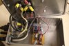
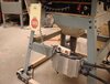
I have a workshop. Its full of wood chip throwing power tools. Some tools are connected to a vacuum (9amp) that ive designed to come on using just relays. This is because a master switch needs to be turned on to run the appliance so engaging the vacuum at the same time is a simple task. My chopsaw (9amp) however is slightly different where i pull a trigger on the appliance to turn it on so in order to have the vacuum power up after i pull the trigger i need a circuit that will sense the load draw from the chopsaw and trigger a relay that will then turn on the vacuum.

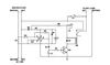
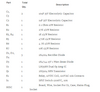
I have this circuit i found that trips a relay when a load is present. this circuit however is meant to turn on a monitor when the computer is turned on. It has a limit of 5 amps and there is no delay on or off of the "slave" device (vacuum)

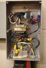
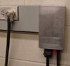
the finished project will be enclosed on a box. It will be plugged into a 120V outlet for power. it will have a receptacle for the saw and a receptacle for the vacuum.

could you help me modify this to work with my 9amp chopsaw and vacuum? And I need the vacuum to wait 1 second before it starts and remain on after i release the trigger on the chopsaw for 3-5 seconds.

Im going to provide the schematic and the parts list for reference. I thank you in advance for your help.
 

Attachments

  • load switching circuit.PNG
    load switching circuit.PNG
    12.2 KB · Views: 488
  • Parts List.PNG
    Parts List.PNG
    7 KB · Views: 316
Hi

a safer approach would be to use a current sensor that provide galvanic isolation between your circuit and the AC mains.

either a current transformer or a Hall effect sensor would be good. I would use a hall sensor because they are small and cheap.

The sensor could be used with an opamp to energize a relay when load current is sensed.
 
the good news is i haven't committed to anything yet.
Ive only read about using hall sensors for this but found no actual application to model from.
i understand the benefit of isolating the circuit from the AC and i can get a lm324n to power a 12v relay.
if you could help select the right hall transistor and help me design this project i would appreciate it?
 
That circuit is badly designed and I'd say it is downright dangerous - if the load resistor fails the neutral is disconnected, not live..

You can buy current sensing relays on ebay, eg.

Add a power relay to switch the vac, with a resistor & capacitor connected to the coil for the pull-in & drop-out delays.

Or you could add an off-delay or multifunction timer set as off delay, such as this:
**broken link removed**
 
Years ago I designed a control for starting a ShopVac from my table saw. If I started the ShopVac at the same time as I started the saw the breaker would trip. So I had the circuit delay the ShopVac start about 2 seconds after the saw. I also had a 10 second shutoff of the ShopVac after I shut off the saw, to continue dust pickup until the blade stopped spinning. Worked great and is still in use today. Funny thing is I posted the circuit on an Electronics forum and shortly there after there was a commercial version that popped up on the market. What are the chances that someone would independently come up with a system with the exact same features as mine. iVac was the first. You can also buy them under the name i-Socket from DGC Products. I also see someone has a DIY version: ShopVac control
 

Attachments

  • ShopVac Delay 4.bmp
    866.3 KB · Views: 257
Last edited:
That circuit is badly designed
im glad i posted it here first before i attempted to build it.
i know i can buy the device all neatly packaged for 35.00 but i thought it would be cool to make it. i learned so much from this group on my last project. i knew nothing then and i know not too much more now but i do understand some concepts. Ive looked at the relay you suggest and it is nice but it looks like it needs the Adrino to make it work. i would like to avoid using software to control it.
 
Years ago I designed a control for starting a ShopVac from my table saw
totally cool. i had seen the video you referenced and its nice but he uses software to control it. i would like to make one that is just hardware controlled. but thank you for sharing your experience with me.
 
Just my opinion on this. While things like the instant on for the vacuum are fine with most tools I wouldn't use one for a chop saw. A tables saw, planer or most other tools are on for long periods of time and it useally takes a short while from starting the machine and actually making chips. That gives the vac time to start pulling them from the tool. A chop saw is on and off so quickly in most cases, that the vac would just start pulling air when the cut is over. I would put a toggle or other on off switch at the chop saw and manually start the vac when using it.
 
A chop saw is on and off so quickly in most cases
collecting saw dust from the chop saw is difficult at best. The setup for this is a 20" square cone placed behind the saw to catch as much of the chips as possible. and the trigger that i would like designed will delay the vac from turning off for 3-5 seconds to clear the debris from the hose.
 
Just my opinion on this. While things like the instant on for the vacuum are fine with most tools I wouldn't use one for a chop saw. A tables saw, planer or most other tools are on for long periods of time and it useally takes a short while from starting the machine and actually making chips. That gives the vac time to start pulling them from the tool. A chop saw is on and off so quickly in most cases, that the vac would just start pulling air when the cut is over. I would put a toggle or other on off switch at the chop saw and manually start the vac when using it.

You could easily design it so it had different time delays (including instant) from different sockets. Or use a decent supply, so breakers don't trip :D However, continuing running for a few seconds afterwards would still be a good idea.

The obvious choice these days would be to do it with a microcontroller, much simply and easier, and much more versatile - although
KMoffett's circuit is fairly interesting (I hope his reed relays have diodes in them though?).
 
I doubt that the small inductive spike from a reed switch is sufficient to damage the associated transistors. They've been switching on and off for many, many years without a problem. But, if you want to add them it won't hurt. I do have to confess that the power-on delay and power-off delay circuit designs came from Bill Bowden's website: Power on/off delay
I had also added a switch on the on/off-delay timer circuit to manually run the ShopVac.
 
Last edited:
the power-on delay and power-off delay circuit designs came from Bill Bowden's website: Power on/off delay
its been a while since ive seen a web page designed like that. when HTML was in its early stages. only colors for background was grey and times new roman was the only font. we had left,right, and center for justification and not much else.

The on delay and off delay is what i need to add to this project. if you could be so kind to help me string this together so it will work with my project id appreciate it.
 

Attachments

  • delay on.gif
    delay on.gif
    2 KB · Views: 300
  • delay off.gif
    delay off.gif
    2.5 KB · Views: 236
Years ago I designed a control for starting a ShopVac
i did not realize you supplied the schematic for your design. im going to study it. if i have any questions may i pass them by you? And i do thank you so very much for sharing your design with me.
 
I doubt that the small inductive spike from a reed switch is sufficient to damage the associated transistors. They've been switching on and off for many, many years without a problem. But, if you want to add them it won't hurt.

I would imagine it's easily enough to do damage, it's an inductor just like any other - but they might have internal diodes, the last reed relays I bought did - bit of a shock actually, and I had to make sure of connecting them the correct way.
 
Already done. Look at my schematic. The circuit above RLY1's contacts is all done. If you don't use my current detection portion (lower circuit) then you need to provide something the to replace RLY1's contact closure. Also. the 12vdc supply. I like gutted smps wall warts. Their easy to install inside cases that already have 120AC lines going in anyway.
Ken
 
I would imagine it's easily enough to do damage, it's an inductor just like any other - but they might have internal diodes, the last reed relays I bought did - bit of a shock actually, and I had to make sure of connecting them the correct way.
I will have to get back to the bench and look at the CEMF with a scope. For the ones I used the inductance must be pretty low with only an air core. I'll have to see if I still have any in the relay "junk box".
 
Look at my schematic.
could you tell me what these are
SSR
F1
i see that R4a and R6a are listed variables but what are R4b and R6b
T1 what kind of transformer is this? it looks like an 18V AC transformer.
T2 could you suggest a transformer i could purchase? ive no experience in modifying one. Why did you modify this one?
 
could you tell me what these are
"Solid State Relay" used to switch on the ShopVac
A fuse
i see that R4a and R6a are listed variables but what are R4b and R6b
Resistors in series with the associated variable resistor to limit its range.
T1 what kind of transformer is this? it looks like an 18V AC transformer.
It 's a step-down power transformer as part of the 12VDC power supply.
T2 could you suggest a transformer i could purchase? ive no experience in modifying one. Why did you modify this one?
This was a standard open frame, parallel bobbin, step down, 24VAC power transformer from my junk bin. I removed the secondary winding and replaced with 3 turns of heavy gauge wire to make a current sensing transformer to detect the saw current .

At this point I'm getting uncomfortable. Your lack of knowledge , though OK for analyzing the circuit components and operation, becomes dangerous when actually trying to build a device that involves possable direct contact with 120VAC. Sorry, but I would recommend "buying" an automatic switch.
Ken
 
At this point I'm getting uncomfortable. Your lack of knowledge , though OK for analyzing the circuit components and operation, becomes dangerous when actually trying to build a device that involves possable direct contact with 120VAC. Sorry, but I would recommend "buying" an automatic switch.
i thought you might suggest that but i do know things. i just did not understand what your references were. i assure you ive had lots experience with high and low voltage. I was the General Contractor on my own homes construction. I did all the electrical wiring myself. connected hundreds of lights and switches. Installed electrical panels, and was recently the electrician on my own swimming pool. did the high voltage and the low voltage. I programed the pools automation too. and I knew nothing when i began. That is just the kind of person i am. I also have junk bins full of electronics, switches, relays, and now that you have confirmed what T1 is im sure i can find one in my transformer bin. I dont mean to ramble but i also make furniture. Never knew a thing about it a few years ago but ive made some pretty incredible things. And Ive never lost a single digit. ive got tools in my shop that can cause more damage that 110V (lol) What im trying to say is i can learn and be cautious at the same time.

Im not angry or mad by your comments. not one bit. if your still uncomfortable helping me i completely understand.
 
OK. I dug through my photo library and came up with these of the wire mold mounted saw control box and the ShopVac control box. There is a 2-wire cable with 1/8" phone plugs that link the two boxes. I think forgot to show the second 12vdc power supply in the ShopVac control box in the schematic. The 12VDC supplies are gutted wall warts. but they are not always easy to remount safely.

In another project I added a knee switch to the Delta table saw. With an added feature of a remote On/Off cabled pendent. That was so I could start and stop the saw when I was ripping an 8' piece of material while standing 8' from the knee switch. ;) Now I would use RF wireless.

Ken
 

Attachments

  • RemoteSwitch5-1.JPG
    RemoteSwitch5-1.JPG
    51.2 KB · Views: 243
  • RemoteSwitch4.JPG
    RemoteSwitch4.JPG
    46.4 KB · Views: 233
  • RemoteSwitch3-2.JPG
    RemoteSwitch3-2.JPG
    51.6 KB · Views: 245
  • RemoteSwitch2.JPG
    RemoteSwitch2.JPG
    52 KB · Views: 222
  • RemoteSwitch1.JPG
    RemoteSwitch1.JPG
    36.9 KB · Views: 235
  • Knee switch.JPG
    Knee switch.JPG
    45.3 KB · Views: 247
Status
Not open for further replies.

Latest threads

New Articles From Microcontroller Tips

Back
Top