Continue to Site

Welcome to our site!

Electro Tech is an online community (with over 170,000 members) who enjoy talking about and building electronic circuits, projects and gadgets. To participate you need to register. Registration is free. Click here to register now.

  • Welcome to our site! Electro Tech is an online community (with over 170,000 members) who enjoy talking about and building electronic circuits, projects and gadgets. To participate you need to register. Registration is free. Click here to register now.

Audio Equalizer in FB Loop

Status
Not open for further replies.

solis365

New Member
I am trying to build a small desk-sized audio amplifier. I salvaged an old stereo cd player from the 90s and got an appropriate transformer (0-25V secondary) and an audio amplifier chip, the Sanyo LA4282 (Datasheet)

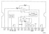
I have separated the block diagram in the attachment.

If you will notice, pins 1 and 6 are labeled "NF"
I am not sure what this means but they do allow one to connect to the feedback network - sort of. The problem is there is always the 300Ω input resistor in the way.

I would like to attach a feedback network for bass, midrange, and treble adjustments, such as a 3-band Baxandall equalizer network. (I read about it **broken link removed**), but any equalizer network will do. I have not researched them exhaustively yet.

The requirements of a passive Baxandall network are low source impedance and high load impedance - in the feedback loop, this seems perfect! The output of the power amp will be low impedance and the input should be high.

The problem is I am always going to connect my feedback network in parallel with the existing 30k/300 gain network, so I don't think it will work.

Would it be possible to do this or would I have to do my equalizing in a preamp stage?


EDIT - I am not looking for audiophile quality or I would have bought a better chip, the one I salvaged seems... merely okay. I may end up buying one anyway if I can't get the FB equalizer to work (one with a more easily accessed feedback network). If I do need to buy one I would appreciate suggestions for a 10W/ch stereo amp chip! I cant go much higher due to speaker and transformer limitations. I do not want it to sound like a 741 "project" audio amp though. Something at least halfway listenable.
 

Attachments

  • LA4282_BLOCK_DIAG_PINOUT.jpg
    LA4282_BLOCK_DIAG_PINOUT.jpg
    51.5 KB · Views: 899
Last edited:
The resistors built into the chip set the basic gain of the amp...Look at the typical app circuit..it shows 1 pin decoupled with a 100mfd cap...

Your tone controls can go before the input of the amp...An active Baxendall cct will minimise insertion loss, maintaining the input sensitivity of the amp..

Yes that makes sense. What opamp would you recommend for an active baxendall to keep the best sound quality possible?
 
I would appreciate suggestions for a 10W/ch stereo amp chip! I cant go much higher due to speaker and transformer limitations. I do not want it to sound like a 741 "project" audio amp though. Something at least halfway listenable.
National Semiconductor has a lot of integrated audio power amps. I built a good amplifier out of them to drive the center channel speakers for my TV. Go to their website and look under their audio section.
 
National Semiconductor has a lot of integrated audio power amps. I built a good amplifier out of them to drive the center channel speakers for my TV. Go to their website and look under their audio section.

Ah yes. I am familiar with things like the LM3886 and LM3875 and LM4870 but I had previously been only googling for "10W stereo amplifier" and not finding anything. Their website probably will make it easier to find...
 
Doesnt have to be a JFet op amp....anything like the 741 will do..
IMHO, garbage grade amps like a 741 do not have enough slew rate for good transient response, so I don't recommend them for audio applications. I liked the LF356 because it has good slew rate, it's unity gain stable, and it's low noise. There are lots of good op amps, but I don't think 741 types are good enough for audio use.
 
Last edited:
Doesnt have to be a JFet op amp....anything like the 741 will do..
No.
A 741 opamp is 41 years old. Its max output frequency is only 9kHz but most people can hear 20kHz. It is noisy (hissss).
Audio opamps work perfectly up to 100kHz. They are low noise.
 
Philips and ST Micro have more than 100 amplifier ICs for car radios with about 10W output. But they say the output is 20 Whats.
 
Philips and ST Micro have more than 100 amplifier ICs for car radios with about 10W output. But they say the output is 20 Whats.

I will look into it. Need 10W per channel. When a chip is advertised as "20W stereo amplifier" does it mean 10W per channel or 20W per channel?

bountyhunter said:
IMHO, garbage grade amps like a 741 do not have enough slew rate for good transient response, so I don't recommend them for audio applications. I liked the LF356 because it has good slew rate, it's unity gain stable, and it's low noise. There are lots of good op amps, but I don't think 741 types are good enough for audio use.
audioguru said:
No.
A 741 opamp is 41 years old. Its max output frequency is only 9kHz but most people can hear 20kHz. It is noisy (hissss).
Audio opamps work perfectly up to 100kHz. They are low noise.
exactly, it will amplify sound but not of any sort of quality. This is a project I intend to listen to ;)
 
Most car radio amplifier ICs advertise 20 Whats. Most car radios advertise 200 Whats. Phoney-baloney numbers.

It is 20 watts per channel into 4 ohms with a 14.4V supply (too high) and a horrible-sounding 10% distortion because the volume control is turned up too high.
One amplifier IC advertises 45 Whats when its input is a square-wave.
Does anybody listen to blasting acid-rock anymore?
 
The high power car amps have built in switching power supplies that generate high voltage rails to run their amplifiers from. If you are using the 14V car voltage, your maximum power with a 4 Ohm speaker is about 20W RMS using a bridge amplifier. With a single sided (ground referenced) setup, you can get about 6W RMS with a 4 Ohm speaker. Some car makers used to parallel two 3.2 Ohm speakers on each line for a net 1.6 Ohm impedance to get more power out from a single sided design. We made a part called the TDA 2003 which could output 5A peak current into a 1.6 Ohm load which means it could drive the 1.6 Ohm loads in a 14V application. Sound quality was hardly superior.
 
Does anybody listen to blasting acid-rock anymore?

Maaaaaaaybe :rolleyes: Just kidding. Well, I don't THINK it's acid-rock... *checks wikipedia*

I realize most chips advertise their maximum power at a horrible THD level... sigh.

I cannot exceed 10W however as I do not want to destroy the speakers I have, which are only rated at 10W. I do not imagine they will be turned up particularly high very often, if at all. However I do not want to blow them out if the volume knob gets bumped or something of that nature.

Is there a way to limit the output power by shunting current to ground past a certain threshhold? Is this ever done? It would sound terrible if the protection circuitry started to kick in, but as long as you kept it below the trip level it might sound better as you could use a higher-power amp not as near to its maximum output... unless the protection circuitry interacted unfavorably with the output of the amp and the speaker. Any thoughts on this method?
 
If your speakers are made by a well known manufacturer then the rated power is the continuous power. You never listen to a sound that is continuous. The average power of music is 1/5th to 1/10th to the maximum power.
 
With "typical" efficiency stereo speakers in an average room, you will probably be listening to less than one Watt average power and less than 10W peak even when the music is pretty loud.

I have Infinity Qc speakers which are pretty low efficiency and even at volume levels approaching "live" sound, I almost never clip the 50W LED on my peak reading power meter.
 
they are Sharp CP-C406, 8ohm

Rated Power: 10W
Max. Power Handling Capacity: 20W

So if they are 10W continuous and music is 1/5th continuous power... I might get away with something like a 40W/ch amp?
 
The cheap Sharp CP-C406 music system is rated for 20 Whats Peak Music Power Output which might be only 1 real Watt per channel. They do not rate the speakers separately.
 
Ah...

yes it is quite cheap. My project is to knock it down in size a bit, i.e. just a small board in an enclosure with small transformer and small audio amp chip, meant to take line-level signals. However I may end up looking into better speakers and a new amp IC as I do not think it will sound great. Plus the gigantic (relatively speaking) speakers kind of ruin the whole "compact" concept I was going for.

At this point its just an experiment to see if I can get something that sounds reasonable out of it.

PS - I like your "Whats" vs Watts system :D
 
Status
Not open for further replies.

Latest threads

New Articles From Microcontroller Tips

Back
Top