The ratio from no distortion to 10% clipping distortion is 0.7 times. So 6.5W at 10% distortion with a 15V supply means that the amplifier begins clipping at 4.55W (simplified calculations). The difference in volume between 9W and 4.5W is small. You will not hear the difference between 4.55W and 4.5W.
Amplifiers have a power supply hum rejection spec where the ripple is attenuated. It should be very low at the output of the amplifier.
Audioguru,
Thanks for the advice. I'll ditch the LM317, change the supply voltage to 15V, and also forget about placing a voltage regulator at the LM2588 input.
-The Nat Semi's software WILL PROVIDE you with both an annotated schematic and a Bill of Materials which lists the value AND full description of each component.
See the attached file of an example circuit which I had run previously.
Schmitt Trigger,
I'm sure that the software will provide me with the info you stated, but I just can’t figure out how to work it. The problem I keep running into is I can't figure out how to load the adjustable version of the LM2588. Whenever I select the LM2588 the schematic and component values are for the 12V version and I can figure out how to change that. Maybe I'm slower than the average bear but I’ve seriously spent hours trying to figure it out. I know it's asking a lot but if you have time would you mind seeing if you can run the software for the following conditions:
Device: LM2588-ADJ
Input Voltage: 5 - 8V
Output Voltage: 15V
Max output current: 800 mA
For the current requirement I looked at the data sheet for the TDA2003 and found that for a 15V supply across a 4 Ω load the maximum power output would be 6.5W. Also from the data sheet the maximum power dissipation looks to be around 3W. So:
6.5W + 3W = 9.5W, I = P/V = 9.5W/15V = 633 mA.
I just bumped it up to 800 mA for a little buffer. Does that seem reasonable?
I would really appreciate your help with the software. Thanks in advance.
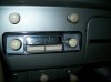
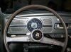
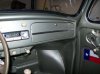
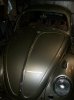
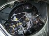
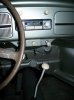
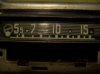
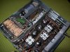
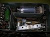
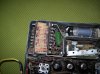
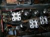
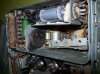
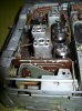
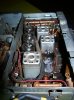
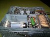
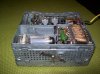
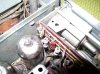
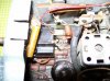
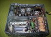
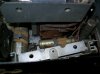
Also, as promised here are some pictures of the VW radio. There are actually pictures from two different radios here. The working radio is installed in the car and my friend didn't want to take it out because he said it is a major pain in the a$$ to get it back in. However, he has a second non-working radio that he used for parts. It is almost complete and is just missing one of the tube amplifiers. I hope it satisfies your curiosity. Enjoy.
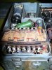
And last but not least:
The plan seems too complex and somewhat wrong for the task.
If it will stay with one speaker to keep originality, the MP3 source can have both earphone or better line-out channels merged and fed to the radio volume potentiometer with a selector switch.
Is that a vacuum tubes radio ? Is it 6 V ?
The 5V MP3 power source can be obtained from the 6V VW electrical with a couple of 1A Si diodes in series to bring it to around 5V. A 7805 is not a good choice. Perhaps a 2950-05 if you really want regulation.
Externet,
I know you made this reccomendation much earlier in the thread. I just wanted to let you know that I suggested the idea to my friend but he was much more receptive to a solution that didn’t require doing anything to the antique and expensive radio. Also, your solution was very simple and would have taken away my project.

Anyway, just didn’t want you to think I was blowing you off. Thanks for the input.