Continue to Site

Welcome to our site!

Electro Tech is an online community (with over 170,000 members) who enjoy talking about and building electronic circuits, projects and gadgets. To participate you need to register. Registration is free. Click here to register now.

  • Welcome to our site! Electro Tech is an online community (with over 170,000 members) who enjoy talking about and building electronic circuits, projects and gadgets. To participate you need to register. Registration is free. Click here to register now.

Audio Amp Component Selection

Status
Not open for further replies.

vne147

Member
Hello again everyone. I am helping a friend with a project for his car. He has an old 1957 VW bug that he is restoring. One of the modifications he wants to make is he wants to be able to plug in an mp3 player and have it play through the car’s speaker. The car has only 1 speaker and it is a 5W 4Ω speaker. Also, the car’s electrical system is only 6V. What I am planning right now is the following.

Use a DC-DC converter to boost the 6V to 9-12V. Use the 9-12V to power an amplifier that will amplify the mp3 player’s output, and then output from the amplifier to the speaker. I’ve found a relatively cheap amplifier IC that I think would work well for this application but I have a few questions.

Here’s the data sheet for the amplifier IC:

https://www.st.com/stonline/books/pdf/docs/1523.pdf

Here are my questions:

  1. Is this component suitable?
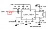
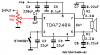
  2. On page 3 of the data sheet there are 2 circuit diagrams. Figure 1 is a bridge application. I’m assuming that bridge is synonymous with mono. Is this correct? This will be a mono application.
  3. Also in the same circuit diagram, the capacitors external to the amplifier IC aren’t all represented with the same symbol. Some of the capacitors symbols are one empty box next to a solid box while others are two solid boxes. Do these represent different capacitor types I should use while building this circuit (i.e. electrolytic vs. ceramic)?

Also, the DC-DC converter I’m looking at right now to boost the car’s voltage is this:

https://www.fairchildsemi.com/ds/FA/FAN5236.pdf

Would this be a suitable component?

What I’m thinking of doing right now is taking the ≈ 6V from the car and putting into a 7805. I’d have some capacitors to give the DC-DC converter a nice stable 5V. Then have the DC-DC converter output 9-12V to the amplifier IC. Then the output from the amplifier will go directly to the speaker.

What does everyone think of this plan? I’ve never worked on any audio projects before so any insight or suggestions will be helpful. Thanks in advance.
 
The plan seems too complex and somewhat wrong for the task.

If it will stay with one speaker to keep originality, the MP3 source can have both earphone or better line-out channels merged and fed to the radio volume potentiometer with a selector switch.
Is that a vacuum tubes radio ? Is it 6 V ?

The 5V MP3 power source can be obtained from the 6V VW electrical with a couple of 1A Si diodes in series to bring it to around 5V. A 7805 is not a good choice. Perhaps a 2950-05 if you really want regulation.
 
Is that a vacuum tubes radio ? Is it 6 V ?

Yes and yes.

So if I understand this correctly, by feeding the combined mono output of the mp3 player into the volume potentiometer of the existing radio, I could use the amplifier built into the radio. Is this correct? Would I only need the selector switch for those two wires (the wire from the mp3 player and the existing wire inside the radio)?

The 5V MP3 power source can be obtained from the 6V VW electrical with a couple of 1A Si diodes in series to bring it to around 5V. A 7805 is not a good choice. Perhaps a 2950-05 if you really want regulation.

I don't think he is interested in getting a power source for the mp3. I think he is just planning on running it off of batteries while it's in the car but I'll run the idea by him.


All this aside, I am a little hesitant to tinker with the existing radio because it is original to the car. If I did screw something up it would likely be difficult and expensive to repair or replace.
 
Last edited:
The TDA2025 will melt if it tries to power a 4 ohm speaker with a 12V (13.8V) supply.
It is designed for a 6V supply where its output at clipping is 2.2W into 4 ohms when both of its amplifiers are bridged.

Why not use an amplifier IC that is designed for car radios like a TDA7240A that can be mounted on a heatsink and has an output of 15W into 4 ohms with a 13.8V.
Then use a speaker that is designed for a car.

The Fairchild converter takes a higher voltage and converts it into a regulated lower voltage. It does not boost the voltage.

A 7805 regulator needs an input that is at least 7V.
 
... I could use the amplifier built into the radio. Is this correct?
Would I only need the selector switch for those two wires (the wire from the mp3 player and the existing wire inside the radio)?
.

Yes and yes. :) The selector would choose The internal radio receptor or the external MP3 to be routed to the radio existing amplifier. All tinkering inside is fully reversible.
 
Last edited:
The TDA2025 will melt if it tries to power a 4 ohm speaker with a 12V (13.8V) supply.
It is designed for a 6V supply where its output at clipping is 2.2W into 4 ohms when both of its amplifiers are bridged.

I guess I was looking at the power output in the table on page 3. In the bridged configuration, for a 9V supply and an 8Ω load there is a maximum power output of 4.7V. Would it melt because the speaker is only 4Ω ?

The Fairchild converter takes a higher voltage and converts it into a regulated lower voltage. It does not boost the voltage.

Sorry, for some reason mouser has the wrong datasheet linked on their website. Here is the correct data sheet for the DC-DC converter I'm think about using:

https://www.fairchildsemi.com/ds/FA/FAN5336.pdf
 
Last edited:
A friend of mine (back in the late 70s) also had a 1954 VW. It was also a 6 volt system, and had a vacuum tube radio, AM only. The radio itself came in two separate chassis. One was the radio itself, and the other was the power supply with a "vibrator" and transformer, which converted the 6 volts to 150 volts or so for the tube's plates.

Is your friend's radio the same? Does it still work? Hopefully you can post some pictures of it!

If you really want to keep the car fully vintage and as original as possible, I would feed the MP3's output to an AM radio kit, and transmit it on an unused frequency. Of course, the sound would be AM-quality.

If you are interested in this approach, here is a suitable kit:
**broken link removed**
 
The datasheet for the TEA2025 is incomplete. it does not show any graphs when it is bridged.
Most IC amplifiers have an amount of heating that is the same as their output power so with a 9V supply its output is 4.7W and its heating is 4.7W.

Its thermal resistance is 60 degrees C temp rise per Watt so its chip will be at (60 degrees x 4.7W) + 25 degrees ambient= 307 degrees C which is more than double its allowed temperature.

The datasheet says it has thermal protection and if it gets too hot then it simply reduces its output power. Maybe it will completely mute.
 
Last edited:
The datasheet for the TDA2025 is incomplete. it does not show any graphs when it is bridged.

I agree, I've kind of been extrapolating or probably more accurately, guessing at the performance in the bridged configuration.

Its thermal resistance is 60 degrees C temp rise per Watt so its chip will be at (60 degrees x 4.7W) + 25 degrees ambient= 307 degrees C which is more than double its allowed temperature.

Is this statement assuming that no heatsink is being used?

Also, what do you think about the DC-DC converter now that I have the correct datasheet linked?

I'm also going to look at the IC you suggested, the TDA7240A.

A friend of mine (back in the late 70s) also had a 1954 VW. It was also a 6 volt system, and had a vacuum tube radio, AM only. The radio itself came in two separate chassis. One was the radio itself, and the other was the power supply with a "vibrator" and transformer, which converted the 6 volts to 150 volts or so for the tube's plates.

Is your friend's radio the same? Does it still work? Hopefully you can post some pictures of it!

If you really want to keep the car fully vintage and as original as possible, I would feed the MP3's output to an AM radio kit, and transmit it on an unused frequency. Of course, the sound would be AM-quality.

If you are interested in this approach, here is a suitable kit:
**broken link removed**

My friend's radio is original to the car, it does still work, and I believe it works the way you describe. When I work on it this weekend, I'll take some pictures and post them. Thanks for the suggestion about the AM radio kit. I don't think he is so concerned about authenticity that he is going to be bothered by a few non-stock wires running around so I think I'm still going to pursue my original idea for now.

Thanks everyone.
 
Last edited:
The TEA2025 does not have mountings for a heatsink. It is in a simple DIP package with a few extra ground pins to carry away some heat to the pcb copper. I quoted the heating with a good pcb design.

With a 6V supply is max output is only 2.2W at clipping into 4 ohms and it will be very warm.
 
One word of caution though.
I played around with an ancient vacuum tube driven am radio from a car many years ago and found out by accident that the volume control circuits where floating at a fairly high voltage in referance to the chassis ground.

By tying into the internal lines going to or from the volume control you could inadvertently be also bringing the MP3 player up to a considerably higher voltage than the car itself is when used as the ground reference. A high impedance audio isolation transformer system may be needed to make the connection between the MP3 units outputs and the old radios volume control circuits.

Its just a thought.
 
Last edited:
Audioguru,

OK I checked out the TDA7240A and it's time for some stupid questions. First off, how would I dynamically vary the power output (i.e. volume control). Also, how do I calculate what the total current draw of the device will be for a given power output? Is it as simple as dividing the power output by the supply voltage (I = P/V)? I know that would be assuming that the device is 100% efficient but that should give me a ball park idea right? Thanks.
 
Simply connect a 20k to 100k log volume control to the input of the input capacitor for a volume control.

The TDA7240A amplifier IC is about 58% efficient at clipping. When its output is at 15W into a 4 ohm load then its heating is 11W. Its total power is 26W which is a current of 1.9A from 13.8V.
 
Like this? Also, after checking out the efficiency vs power output graph in the datasheet, it seems like this amp might be overkill. I am only powering a single 5W speaker. At 5W output, the efficieny drops to ~ 35%. Is there a similar amp out there you could suggest that's rated for a lower power output and would be more efficient in the 5W range? Thanks.
 

Attachments

  • audio_amp.JPG
    audio_amp.JPG
    27.9 KB · Views: 691
Last edited:
No.
Your pot is a rheostat that changes the volume only slightly.

A volume control must be a variable voltage divider like this:
 

Attachments

  • TDA7240A volume control.PNG
    TDA7240A volume control.PNG
    57.5 KB · Views: 880
Ahhh, I understand now. Also, I edited my last post. Did you see the question about suggesting an alternate amp? Thanks.
 
Most modern cars come with a factory installed 4 channels sound system with 15 real Watts per channel for a total of 60W. The cars are quiet.

You want to use only 5W in a noisy VW bug?

The TDA7240A amplifier has an output of about 8W into an 8 ohm speaker with a 13.8V supply.
 
A modern car is quiet and comes with a sound system with 4 channels each with 15W for a total of 60 real Watts. My car came with 25W per channel x 4 (2 ohm speakers) and a 180W sub-woofer.

You want to hear only 5W in a noisy VW bug?
 
I'm helping a friend who is restoring the car. The speaker originally put in the car was a 5W speaker and for some reason, he wants to keep it.
Then it doesn't matter if it can be heard or not and it doesn't matter what it sounds like. Its most importance is what it looks like.
 
Status
Not open for further replies.

Latest threads

New Articles From Microcontroller Tips

Back
Top