Note: Long post. You might want to get a [fill in name of preferred drink here] before you start this.
OK, that's better. So this is part of my continuing quest to come up with a cheap, simple 3-volt-to-5-volt converter. Think of it as a poor man's Minty Boost. (I would actually like it to be able to supply 9 volts, but so far that seems an unattainable goal.)
So I was reading up on SMPSs, and once more came across the description of classic boost converter topology:
**broken link removed**
I thought to myself: "Self, why couldn't one drive this with a simple transistor oscillator, rather than a fancy-schmancy chip? Why not our favorite li'l oscillator, the relaxation oscillator (aka free-running multivibrator?"
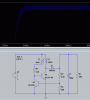
Why not indeed? So that's exactly what I did. Here it is (the LTspice file is attached below):
**broken link removed**
It not only works in LTspice simulation, but also in real life. (Slightly different results, but never mind.) Of course, it comes nowhere near the Minty Boost, which can deliver a hefty 500mA at 5 volts; the best result I was able to get was 6.5 volts at 18mA (with a 390Ω load resistor). The best I could get from the LTspice simulation was 7.7V @ 19.6mA.
I think this idea has promise. Of course, this is just a starting point, if indeed there is some better ending point out there. After all, it is totally unregulated in its current form. Just raw output. (That may be sufficient for some applications that don't require good voltage regulation.) That's one of the issues I ask about below.
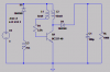
So comparing this to the Minty Boost, I wonder exactly why this is so much more wimpy. After all, if you strip down the Minty Boost to its essentials, you get this:
**broken link removed**
Looks familiar, no? The only difference is that the main works (oscillator and switch) are inside that little chip.
So why can't I achieve at least close to its performance with a more humble circuit?
There are several parameters that are critical to the operation of a boost converter:
to name the main ones.
Having no way to measure frequency here, I have to rely on the simulation as my guide. LTspice tells me that the switch is being driven at about 300kHz, a respectably-high frequency. But of course, one question is whether the on-time parameter is really what it should be. Especially since the multivibrator waveform (again, the simulated waveform) looks like this:
**broken link removed**
Not very symmetrical. Now, it would be interesting to learn what effect making the multivibrator "lope" would have on the converter performance--that is, making the two times unequal (different R or C sizes). Any thoughts on this?
The inductor value also has me mystified. According to my book on power supplies, the formula for the inductor value is
L = Vin * Ton / Ipk
which gives me a value somewhere in the millihenry range, not microhenries. (Using Ton ~= 2.3µS.) (Here, we're supposed to size the inductor based on the minimum current, which makes it larger.)
So which way should I go here: where should I be frequency-wise? What's the best way to match the inductor to the switching frequency? How about using something beside a BJT for the switch: MOSFET? something else?
Thinking ahead, it occurs to me that instead of just sticking a 7805 in there to waste some electrons and give me 5 volts, maybe I could come up with a quick-and-dirty regulation scheme, like frequency-modulating the multivibrator (basically implementing some kind of VCO). Possible?
The fact that this works as well as it does is intriguing to me, and leads me to belive that there's much more potential here. Now imagine that this could be cranked up to deliver 9 volts: that would be a really nice way of eliminating 9-volt batteries in small electronic devices.
OK, that's better. So this is part of my continuing quest to come up with a cheap, simple 3-volt-to-5-volt converter. Think of it as a poor man's Minty Boost. (I would actually like it to be able to supply 9 volts, but so far that seems an unattainable goal.)
So I was reading up on SMPSs, and once more came across the description of classic boost converter topology:
**broken link removed**
I thought to myself: "Self, why couldn't one drive this with a simple transistor oscillator, rather than a fancy-schmancy chip? Why not our favorite li'l oscillator, the relaxation oscillator (aka free-running multivibrator?"
Why not indeed? So that's exactly what I did. Here it is (the LTspice file is attached below):
**broken link removed**
It not only works in LTspice simulation, but also in real life. (Slightly different results, but never mind.) Of course, it comes nowhere near the Minty Boost, which can deliver a hefty 500mA at 5 volts; the best result I was able to get was 6.5 volts at 18mA (with a 390Ω load resistor). The best I could get from the LTspice simulation was 7.7V @ 19.6mA.
I think this idea has promise. Of course, this is just a starting point, if indeed there is some better ending point out there. After all, it is totally unregulated in its current form. Just raw output. (That may be sufficient for some applications that don't require good voltage regulation.) That's one of the issues I ask about below.
So comparing this to the Minty Boost, I wonder exactly why this is so much more wimpy. After all, if you strip down the Minty Boost to its essentials, you get this:
**broken link removed**
Looks familiar, no? The only difference is that the main works (oscillator and switch) are inside that little chip.
So why can't I achieve at least close to its performance with a more humble circuit?
There are several parameters that are critical to the operation of a boost converter:
- Switching frequency (the multivibrator frequency in this case)
- The "on time" of the switching waveform (in other words, the duty cycle). See below for more on this.
- The inductor value
to name the main ones.
Having no way to measure frequency here, I have to rely on the simulation as my guide. LTspice tells me that the switch is being driven at about 300kHz, a respectably-high frequency. But of course, one question is whether the on-time parameter is really what it should be. Especially since the multivibrator waveform (again, the simulated waveform) looks like this:
**broken link removed**
Not very symmetrical. Now, it would be interesting to learn what effect making the multivibrator "lope" would have on the converter performance--that is, making the two times unequal (different R or C sizes). Any thoughts on this?
The inductor value also has me mystified. According to my book on power supplies, the formula for the inductor value is
L = Vin * Ton / Ipk
which gives me a value somewhere in the millihenry range, not microhenries. (Using Ton ~= 2.3µS.) (Here, we're supposed to size the inductor based on the minimum current, which makes it larger.)
So which way should I go here: where should I be frequency-wise? What's the best way to match the inductor to the switching frequency? How about using something beside a BJT for the switch: MOSFET? something else?
Thinking ahead, it occurs to me that instead of just sticking a 7805 in there to waste some electrons and give me 5 volts, maybe I could come up with a quick-and-dirty regulation scheme, like frequency-modulating the multivibrator (basically implementing some kind of VCO). Possible?
The fact that this works as well as it does is intriguing to me, and leads me to belive that there's much more potential here. Now imagine that this could be cranked up to deliver 9 volts: that would be a really nice way of eliminating 9-volt batteries in small electronic devices.
Attachments
Last edited:
")