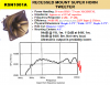
I have never used an awful-sounding cheap piezo tweeter. Motorola invented it many years ago then other companies made the same looking thing.
The sales sheet I have has a smoothed frequency response curve but I know that the peaks and nulls are actually much higher and lower. Its capacitance is rated at 0.13uF.
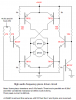
Now that you want to use two tweeters and a 14V supply then the entire circuit can be properly re-calculated.
The power in the tweeters and transistors is highest at high frequencies. I can't remember what is the highest frequency so I will assume 30kHz.
Then two paralleled tweeters have a reactance of 20.5 ohms.
With a voltage swing of 13.6V then the peak current is 663mA. TIP power transistors should be used.
The base current of the output transistors should be 66mA so they saturate well.
The base current of the driver transistors should be 6.6mA so they saturate well.
The base current of the inverter transistor should be 0.7mA so it saturates well.
The sales sheet I have has a smoothed frequency response curve but I know that the peaks and nulls are actually much higher and lower. Its capacitance is rated at 0.13uF.
Now that you want to use two tweeters and a 14V supply then the entire circuit can be properly re-calculated.
The power in the tweeters and transistors is highest at high frequencies. I can't remember what is the highest frequency so I will assume 30kHz.
Then two paralleled tweeters have a reactance of 20.5 ohms.
With a voltage swing of 13.6V then the peak current is 663mA. TIP power transistors should be used.
The base current of the output transistors should be 66mA so they saturate well.
The base current of the driver transistors should be 6.6mA so they saturate well.
The base current of the inverter transistor should be 0.7mA so it saturates well.