I learnt about more about cutoff frequency (fc) of capacitor.... BUT...where is the 10K load resistor to ground (series with 330nF) on Mod 4 to form High Pass Filter?
Every coupling capacitor has a resistor load to ground and forms a highpass filter.
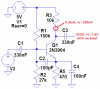
1) My Mod4 circuit has a 330nF coupling capacitor from the electret mic to the input of the preamp transistor:
The preamp transistor operates at a collector current of 0.28mA and the datasheet for the 2N3904 has a graph showing its typical current gain at that current is 100 and another graph shows its base-emitter input impedance is 11k ohms. Then the transistor's current gain times the emitter resistor value of 470 ohms is 47k. The total input resistance of the preamp transistor is 11k + 47k= 58k ohms.
The 160k and 30k biasing resistors for the preamp transistor are effectively in parallel with a total of 25.3k which is parallel to the 58k of the transistor for a total of 17.6k.
The electret mic and the 10k resistor powering it is about 2.7k in series with the coupling capacitor so the total resistance is 17.6k + 2.7k= 20.3k.
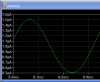
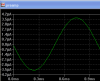
Then the cutoff frequency is 24Hz.
2) The output of the preamp transistor has an impedance of about 10k ohms and its 330nF coupling capacitor feeds the oscillator transistor that also has an input impedance. This forms another highpass filter that combines with the first filter causing the output to be -6dB at the combined frequency. Then the -3dB cutoff frequency of the entire circuit is higher than 24Hz and might be 35Hz.
I found two type of attenuator stage for FM (attenuator B) and for MP3 (attenuator A), look at schematic. What is the difference and its difference application among them?
Attenuator A shorts the signal which might overload the signal source. Attenuator B is a volume control.
Another, I found a sentence- "our ears perceive sound in a logarithmic fashion." Also you said about this once. What they mean?
Yes, our hearing's sensitivity to loudness is logarithmic then we can hear a very wide range of loudness from a whisper to a nearby jet airplane.
3dB is double or half the power. But it sounds only a little louder or a little less loud.
10 times the power sounds twice as loud and 1/10th the power sounds half as loud. That is why a volume control has an "audio taper" (it is logarithmic).

 . Your few calculation inpired me lot. Can you calculate the value and its watt of this resistor?
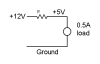

") VCD Player. It has lost its remote control functionality so sound of its internal amplifier was horriable high. I found amplifier's input point and set 2 Potentiometer as a gain controller for L and R. Thus I made volume controller. There I found two type of attenuator stage for FM (attenuator B) and for MP3 (attenuator A), look at schematic. What is the difference and its difference application among them?
VCD Player. It has lost its remote control functionality so sound of its internal amplifier was horriable high. I found amplifier's input point and set 2 Potentiometer as a gain controller for L and R. Thus I made volume controller. There I found two type of attenuator stage for FM (attenuator B) and for MP3 (attenuator A), look at schematic. What is the difference and its difference application among them?