Continue to Site

Welcome to our site!

Electro Tech is an online community (with over 170,000 members) who enjoy talking about and building electronic circuits, projects and gadgets. To participate you need to register. Registration is free. Click here to register now.

  • Welcome to our site! Electro Tech is an online community (with over 170,000 members) who enjoy talking about and building electronic circuits, projects and gadgets. To participate you need to register. Registration is free. Click here to register now.

Analysing Power Amplifier circuits-General discussion

Status
Not open for further replies.
Q1 & Q1 appear to be an attempt at a voltage reference to bias the current mirror composed of Q6 & Q7. I wouldn't guarantee it's performance, however.
 
Last edited:
Another Circuit

I welcome any views on this circuit....
 

Attachments

  • ampcct9..png
    ampcct9..png
    12.2 KB · Views: 310
Alright, no more weird circuits....Im curious as to the effect of Q7-8 in the circuit?Does anyone know whats its purpose?
 
Last edited:
Alright, no more weird circuits....Im curious as to the effect of Q7-8 in the circuit?Does anyone know whats its purpose?
Q7-Q8 is a darlington pair connected to the collector of Q3. In the case that Q3 conducts anything, Q7-Q8 slams the output drivers against the Vcc rail producing a square wave. If C3 is the right value then Q2 will try to cut off the base current to Q3 and it will be an oscillator but its stability depends on R7. If Q4 is the right geometry then it will provide some compensation to Q2. But Q5 and Q6 are a current sink and maximize the voltage gain of Q7 and Q8 so they provide the best possible square waves.
 
In the previous "weird" "strangest" circuit ever lol, i had asked What does the circuit Q1-2 achieve?

I got the response:
Q1 & Q1 appear to be an attempt at a voltage reference to bias the current mirror composed of Q6 & Q7. I wouldn't guarantee it's performance, however.


So now i would like to know if the reference voltage circuit is better in the last circuit posted compared to the weird cct?
 
Please don't post anymore weird circuits.

Aren't you the least bit excited to see something "new" ( that's ironic seeing that it came from the 70's)?:D
 
Lol, what's a weird circuit? :D
I copied and pasted some comments about these weird circuits in this theread:

"It's not a real design, various bits are missing and many of the values are completely wrong.
It needs throwing away and starting from scratch.
A recipe for disaster. It's more likely to cause a chain reaction self destruct.
Looks rubbish to me?
It is the strangest amplifier that I have ever seen.
Where did you find this one?
Like your previous circuit, it doesn't look like a complete working design, and this one even less so.
It's still non-functional, nothing like a working amplifier.
It looks like someone who didn't know anything about electronics saw a circuit once, and then tried to draw it from memory a week later."
 
Yes, this is yet another total piece of rubbish - no wonder you never hear of amplifers made in South Africa.

None of the 'designs' you've posted would work - they are just rubbish, and bear little resemblance to anthing that would.
 
I know it doesn't work.

I just found it funny how you labled it a weird circuit. :D
 
I'm young and inexperienced..........I'm just trying to understand power amplifier ccts and get views...........i don't know what I post works or not....and that's why i welcome any views....
 
In the previous "weird" "strangest" circuit ever lol, i had asked What does the circuit Q1-2 achieve?

I got the response:


So now i would like to know if the reference voltage circuit is better in the last circuit posted compared to the weird cct?

In your last circuit, there was a voltage reference made form Z1 & Q1, which might be the only functional part of the design. But it has no compensation for temperature.
 
I tried downloading it MR Goodwin but it was corrupted and cant open up......................................

Read the free book you downloaded here.

Yeah thanks Audioguru, Im going to try downloading that document again now. My net did not download it when i tried yesterday....it was taking forever.....


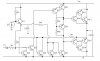
What do R6 and C1 do?

I tried twice to download it...it gave me the same error msg:


Foxit Reader: Format error: not a PDF or corrupted.....
 
Status
Not open for further replies.

Latest threads

New Articles From Microcontroller Tips

Back
Top