Continue to Site

Welcome to our site!

Electro Tech is an online community (with over 170,000 members) who enjoy talking about and building electronic circuits, projects and gadgets. To participate you need to register. Registration is free. Click here to register now.

  • Welcome to our site! Electro Tech is an online community (with over 170,000 members) who enjoy talking about and building electronic circuits, projects and gadgets. To participate you need to register. Registration is free. Click here to register now.

Advise needed for running LED lights from a powerbank

Status
Not open for further replies.

DaveMK

Member
Hello,

I want to build a smartphone camera rig that has LED lights built in that run from a USB power bank.
I’ve attached a basic design to give an idea of what I’m trying to achieve.

I’ve got no experience with electronics, but can (and have) follow instructions for personal projects.
Can anyone please help with some advise.

I already use an LED light that runs from large camcorder batteries and claims to be 20w, and I’m aiming for the same light oputput.

The areas I need advise on are:

Would I be better going with Cob strips like these:
**broken link removed**

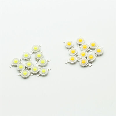
Or chips like these:

Could I run approximately 20w from a powerbank like this:
**broken link removed**

The main frame would be made from plywood. Would I need a heat sync from LED's with such low output?

What components would I need to build, and to be able to dim the light?

Thank you!
Dave
 

Attachments

  • DIY-Camera-rig.jpg
    DIY-Camera-rig.jpg
    574 KB · Views: 376
The LEDs are cheap and No-Name-Brand. Some of them probably will not work properly. Ebay frequently sells fake and/or defective junk.
The 12V LED lamp will not work from the 5V output of the powerbank.
The tiny 3.2V to 3.6V LEDs need a circuit to convert the 5V from the powerbank to the current they need and some way to mount them on a heatsink.
 
You could use something like this:- https://www.ebay.co.uk/itm/USB-to-D...tep-Up-Cable-5-5-2-1mm-DC-1M-BSG/184294766936 to run the light strips at 12 V.

I would suggest you only run one, or at most two, from a power bank. The 12 V strips take 5 W, so at the 5 V output of the USB, that is 1 A. However the converter won't be 100 % efficient so it will be more than 1 A, maybe 1.2 A, so running two from a power bank pushing the limits.

I suggest you use several small power banks. Even the big power bank you liked to is only rated at 2.4 A (corrected from where I put the wrong units). Being larger makes it last longer, not produce a higher power.

Using a power bank like that isn't efficient, but it's an easy thing to put together. You could have a somewhat more efficient set up but it would need electronics to be designed and built, which would be a lot of work.

A power bank has a Li-Ion battery that runs at between 3.4 V and 4.2 V. The power bank has a boost circuit that increases that to 5 V for any battery voltage but that boost circuit has an efficiency of maybe 85%. The converter that I suggested has an efficiency of maybe 85% as well. The LED strips will probably have 3 LEDs in series, maybe 3.2 V each, so 9.6 V and there will be a resistor to limit the current that is also a loss of power, so the efficiency is 9.6/12 = 80%.

The overall efficiency is just under 60%, so less than 60% of the battery power will make it to the LEDs and the rest will be lost in heat in electronic components. If you had a current limiter and ran 3.2 V LEDs from the battery the efficiency would be between 76% with a full battery and 94% with a nearly empty battery. Alternatively you could have a converter to convert the battery voltage directly to the LED voltage, with suitable current control, and you might average 90% efficiency, but you would need to have batteries that are not in a power bank, and the loose LEDs.

So using a power bank, a 5 to 12 V converter and those LED strips means that your batteries need to be 1.5 times as big as with the best circuit. However for making one rig from off-the-shelf components, and having an easy way to charge the batteries, I would recommend accepting some slight limitations.

I agree that a lot of the stuff from Ebay will be poor quality. However most of it works, and with lighting you can see if the overall effect is what you want.
 
Last edited:
Thank you again for both of your posts.

@ Audioguru, thanks for the heads up on ebay and quality and for your advise.

@ Diver300, thanks also for your detailed advise.


As the components to build this are quite cheap, and I already have the powerbank, I’d like to have a shot at building the rig using 12x 1w LED chips. Probably these.

and these heat syncs
**broken link removed**

I understand there will be some limitations, but this light is mainly for fill light, and not to illuminate a large area.

Since making this original post I’ve watched many Youtube videos, and have found these 2 specifically that I feel are close to what I want to achieve, without the ability to dim.


Can I ask a couple more questions please.

These two videos build in a different way.
One uses resistors every 3 chips, one. doesn’t.

Which method would you advise if I was going for 12x 1w chips from the powerbank I initially linked to?

Would you advise the DC USB step up cable

Or a step up supply like this


Any advise for how I could add a dimmer, and what type of dimmer to use?

Sorry for all the questions.
I’ve got very little experience with electronics, but when I get a project in my head, I like to follow it through.
 
It's all getting a bit complicated.

LEDs should be supplied with a current, not a voltage. So if you have a 1W LED that takes 312 mA at 3.2 V, you should supply it with a maximum of 312 mA. The exact voltage across will be near 3.2 V, but may be a bit more or a bit less. You can supply it with less current. Anywhere down to 1/10th or 1/20th will be fine. At really low currents you can get odd effects. At low currents, the voltage won't change much. Maybe 2.8 - 2.9 V for an LED like that at 1/10th of its full rating.

One way to control the current is to put a resistor in series. A common arrangement is 3 LEDs in series, then a resistor. With three LEDs at 3.2 V each, that's 9.6 V so there is 2.4 V across the resistor with a 12 V supply and the resistor needed would be 7.7 Ohms. That method is OK, but it's difficult to dim with any accuracy because when the voltage drops a little bit, the current drops a lot.

There are driver circuits that control the current. They act like an automatic variable resistor to keep the current the same.

There are step-up (or down) circuits that control the current. The more elaborate step-up circuits have a current limit as well as a voltage limit and they can just have the current limit set to what you want, while the voltage limit is set a bit higher, so that the voltage is not much too large if the LED connection breaks.
 
The LED beads ad does not say any important electrical detail like range of voltage or maximum allowed current for you to design a current-limiting circuit (because the ebay seller knows nothing about the junk he sells).

The heatsink ad does not say the type of LED it is designed for or a method to attach the LED (because the ebay seller knows nothing about the junk he sells).

Since the LED beads ad has no detailed spec's then you must measure the voltage of each one and maybe destroy a few to find out how much current is too much.
Since they say each LED survives 1W then I would guess that the average voltage of each white LED is 3.2V. Then its maximum current is 1W/3.2V= 313mA. But the powerbank has a max output current of 2.4A so 12 LEDs will have a max current of 200mA each. The powerbank produces 5V so the resistor for each LED is (5V - 3.2V)/200mA= 9 ohms. Use 10 ohms for safety. The resistor will heat with (5V - 3.2V) squared, divided by 10 ohms= 0.33W. Use a 1W series resistor for each LED..

If you use a voltage stepup device then if one LED fails, they all turn off.

Somebody might make and sell a dimmer.
Edited the resistor value.
 
Last edited:
Thanks again for both of your time and efforts.
To be honest, almost all of that info has gone over my head, and I'm not sure where I need to go from here.
 
Try it and see. Worse case scenario is your battery goes flat earlier than you expected but you'll then know what power you require.

Mike.
 
When selecting LEDs lights for photography, look for LEDs with high CRI (color index). Also, look for color temperature in the 4000 to 4200 range (light reflected off of puffy white clouds) or 5000k (blue sky directly illuminating objects). 2700-3000 gives the sunrise / sunset effect. A halogen bulb is s typically 3200K.

the higher the Calvin number is, the more important the CRI is. Look for 90+ for 4000K. Colors look unnatural with low CRI and the unnatural color looks even more unnatural in photos. .
 
Try it and see. Worse case scenario is your battery goes flat earlier than you expected but you'll then know what power you require.

Mike.
I will do thanks.
I'm going to stick to the parts already linked to and forget about the dimmer for now.
I just need to figure out the resistors and exactly how to wire it together.
 
When selecting LEDs lights for photography, look for LEDs with high CRI (color index). Also, look for color temperature in the 4000 to 4200 range (light reflected off of puffy white clouds) or 5000k (blue sky directly illuminating objects). 2700-3000 gives the sunrise / sunset effect. A halogen bulb is s typically 3200K.

the higher the Calvin number is, the more important the CRI is. Look for 90+ for 4000K. Colors look unnatural with low CRI and the unnatural color looks even more unnatural in photos. .
Thank you for the info. The bulbs I'm going for are 4000K, but there's no mention of the CRI.
 
The video shows 3 battery holders in series but they must be 3.7V rechargeable batteries making 11.1V when they are discharged a little.
Your powerbank makes 5V so the wiring and resistors are completely different.

A cheap white LED is a blue LED with a yellow phosphor in top that you can see then the LED is turned off. It produces no red to make a true white color.
The photo looks like white.
Thank you,
Could you please post a link to the type of resistors you are advising me to use.
Thanks
 
A cheap white LED is a blue LED with a yellow phosphor in top that you can see then the LED is turned off. It produces no red to make a true white color.
The photo looks like white.
Good white LEDs (CRI 90+) have broad spectral emissions and easily cover the red. In fact, the emissions usually extend out well into the 700s of nanometers (way beyond a typical Red LED. Below are some very good and low priced Cree LED emission spectrum.
 

Attachments

  • B2777007-F5A7-460E-B30A-6A5BB8BD9354.jpeg
    B2777007-F5A7-460E-B30A-6A5BB8BD9354.jpeg
    1,000.4 KB · Views: 265
Could you please post a link to the type of resistors you are advising me to use.
I describe wiring and the resistors in post #9. The resistors are available at every electronic parts distributor all over the world.
 
Why are you buying no-name-brand way over-priced junk from China? Did you see the shipping charge? They do not have 8.2 ohms anyway.
At my local electronic parts store they have the needed 8.2 ohms, are good quality and cost almost nothing.
You do not need 1% or metal film. Instead 5% and 1W carbon film are fine and cost less.
 
Status
Not open for further replies.

Latest threads

New Articles From Microcontroller Tips

Back
Top