Continue to Site

Welcome to our site!

Electro Tech is an online community (with over 170,000 members) who enjoy talking about and building electronic circuits, projects and gadgets. To participate you need to register. Registration is free. Click here to register now.

  • Welcome to our site! Electro Tech is an online community (with over 170,000 members) who enjoy talking about and building electronic circuits, projects and gadgets. To participate you need to register. Registration is free. Click here to register now.

A little help with a Proximity sensor and a RPM gauge

Status
Not open for further replies.

Alexanderfitu

New Member
Hi all

First of all, I have always been a tinkerer, but never properly understood the more complicated electrical circuits.

Anywho, I am trying drive a tachometer, that takes 12v pulses from a compression ignition engine (therefore no spark ignition to measure RPM).

My idea is to have a Magnet on the flywheel, then a proximity sensor feeding 12v to the tach when the magnet passes by.

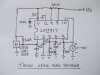
The proximity sensor I am going to use is a Cherry Mp1013:

vss.JPG

This shows it needs a pull up resistor between VCC and Ground. based on a 13V input voltage, what resistor would I need.

Can anybody confirm that my circuit diag here isnt completely wrong :)

rev2.JPG

Thanks in advance

:)
 
The sensor has a max current of 25 mA and you will be using a 12 volt supply. I would start with a max current of 15 mA or an 800 ohm pull up and take that out to about 1 K Ohm. How much does the tach require? Also as to tach input remember as you drew things you will get one pulse per revolution. Is that what the tach expects?

Ron
 
Many Thanks.

I am unaware of the tachs specs at this time as I am watching a couple on ebay that are badly described, but cheap :)

I am assuming if the tach is for a 4 cylinder, I can attach 4 magnets to the flywheel at equal distance, would this work? (increase or decreased based on the number of cylinders the tach is expecting?)
 
I am assuming if the tach is for a 4 cylinder, I can attach 4 magnets to the flywheel at equal distance
A spark-ignition 4-stroke 4-cylinder engine involves 2 sparks per crankshaft rev; so if your tach is intended for such an engine you will probably need only 2 magnets.
 
Is there also a reason I cannot use a reed switch in this situation?
A reed switch will operate for a large number of switching operations, but it will eventually fail from fatigue (likely before the end of the engine life). Better to use a solid-state sensor which will have a much longer life.
 
A reed switch will operate for a large number of switching operations, but it will eventually fail from fatigue (likely before the end of the engine life). Better to use a solid-state sensor which will have a much longer life.

Aha fair enough, I was also told that switch bouncing would be an issue with a reed switch :(

Very helpful lot this forum :)
 
A problem which I experienced with a reed switch was the reed becoming permanently magnetised by repeated passage of the magnet, causing the reed contacts to stick together. This happened after only a few hours of use, with the magnet rotated by a shaft at ~ 30 rpm.
 
A problem which I experienced with a reed switch was the reed becoming permanently magnetised by repeated passage of the magnet, causing the reed contacts to stick together. This happened after only a few hours of use, with the magnet rotated by a shaft at ~ 30 rpm.
Are you sure that wasn't due to the relay load causing the contacts to weld and stick. Reed relays can normally only carry a very small load. What was the load? Was it capacitive or inductive?
 
The sensor you picked should work fine and at about $6.00 USD is likely the most inexpensive you will find. With the simple addition of a pull up resistor to the open collector output it should deliver easily counted pulses. The only downside is that you need to mount magnets without upsetting the balance of the rotating shaft. There are better sensors out there like those that will literally count the teeth on a gear but the get real expensive real quick too. I have worked with reed switches quite extensively including hot buzz testing of them and I don't see a reed switch as a good solution when the sensor you are looking at should work just fine.

Just My Take
Ron
 
This is what i used on a diesel engine in my boat the Hall sensor is simmilar to the one you have. In my case i fixed a magnet to the front pulley on the engine. In one pic i am using a small solenoid coil to pulse the hall sensor @ 50cycles to calibrate the tacho. The VDO tacho ive removed the original circuit in side as it didnt suit my aplication & im only using the meter part with the external tacho IC.
 

Attachments

  • Tacho 3.JPG
    Tacho 3.JPG
    1.8 MB · Views: 254
  • Tacho 4 (2).JPG
    Tacho 4 (2).JPG
    1.7 MB · Views: 244
  • Tacho 4.JPG
    Tacho 4.JPG
    1.7 MB · Views: 283
  • Tacho 5.JPG
    Tacho 5.JPG
    1.7 MB · Views: 254
Right, it turns out that the gauge has only 2 terminals.

One marked G the other Marked A.

I assume it wont need 2 12v feeds then, just the signal and ground?
 
Your circuit should work ok , provided the tacho your using will work on the lower voltage provided by the hall device. Mine didnt thats why i used the IC to drive just the meter movement.
 
There is a big difference here. The circuit debe is using incorporates the use of a frequency to voltage converter. That would be this chip. The pulses from the sensor are converted to voltage that is proportional to the engine speed in RPM. The actual tachometer display being used is in reality a 0 to 10 volt beter scaled to read RPM.

Your sensor does not output an analog voltage as it stands alone. The idea here is to condition the signal for the display. Exactly what display do you have and what type input does it require as in pulses or an analog voltage?

Ron
 
Right that makes sense.

The problem is, that I havent got the sensor yet, but its this one:

**broken link removed**

I am unable to find any specifications on it.

I thought it would increase the needle based on the number of pulses it received, but I think this is unlikely now that I have learned it only has 2 pins ( and therefore doesnt have its own 12v source to drive the needle ) :(
 
Are you sure that wasn't due to the relay load causing the contacts to weld and stick. Reed relays can normally only carry a very small load. What was the load? Was it capacitive or inductive?
The load was <1 mA, resistive (input to a TTL gate). So I think that rules out contact-welding!
 
Status
Not open for further replies.

Latest threads

New Articles From Microcontroller Tips

Back
Top