Hello everyone.
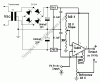
I have constructed this circuit but I want to clarify something which is the fact that I am looking at the output + and - and I am wondering if the output - can be connected to ground as you can see from the circuit, ground is different from output - .
Looking at the website
**broken link removed**
And looking at the instructions for calibration I ran into problems when I decided to use small digital display volt meter which can be attached to the circuit instead of the conventional voltmeters but the issue here is that that voltmeter power supply and its input for displaying measured voltage share a common ground which means that when I connect the output - to the voltmeter which has been powered I am effectively shorting the output - to ground and this affects my circuit as from the circuit ground and output - are different.