It was my error in the way I worded it -- sorry. There are two inputs and two outputs.
The ground and power (black and yellow) provide 9VDC to the lock body. (outputs)
The green wire, what I call the ADC line of the keypad, is a resistor network and provides resistance only when NOT hooked to the lock body (even with batteries in the keypad). When the lock is hooked up to it, it has 3.44VDC applied to it (LaGard lock). Mine is using a 22K resistor attached to the 5VDC power rail. Either way, voltage is connected to ground through the keypad, so the ADC line would be a keypad input, requiring the voltage from the 22K resistor (from the lock) to pass through a resistor in the keypad to ground.
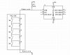
The red wire is an input and controls the LED/piezo.
The keypad does not have a PIC(-like) chip in it, the lock itself contains the :mu:C. If you read the manual a little closer, you will notice that you require a lock body (part number 4100, for example) to make that keypad do anything -- it is simply an analog keypad. I am a distributor for the product, as well as a factory certified tech for the entire product line. I service these locks on a daily basis, which generally entails unit replacement, so I have never really gotten into the schematics of it before -- now it interests me.
")
The batteries are going to be used to power the pic, which will be inside of a safe -- hence the reason to try and keep the wires to a minimum, and not have a Wall-Wart wired to it. There will be times when a Wall-Wart is warranted, but not in this case -- for development, OK -- batteries ain't cheap!
")
So, eric1388, can you point me in the direction of a good regulator for use with 9VDC batteries (I did a quick search this morning and didn't find what I was looking for -- I look again after dinner, but it doesn't hurt to ask!). Oh, thanks, BTW, for the information -- I didn't know the 7805 would drain the battery -- but then I have to confess... I haven't read the datasheet on it too well. I have simply copied what I have seen in various schematics for the power supply portion of my tinkering.
I was at Sayal Electronics today -- man, these guys don't know their A$$ from a hole in the ground without a part number. I looked at their regulator wall for 20 minutes and couldn't find anything on my own (back to the net for some research). I even looked for a 7803 (if that exists, I'll look at that later too) or something similar, hoping I could find get 3VDC regulated for a stepper motor I want to play with, which is 3VDC. I figured it would be a whole lot better than using a resistor to reduce the voltage, as it probably won't work well under load. Well, that's another post... sorry.
Every part I was looking for "they could order" -- L298 or SN754410 H-Bridge, TIP107, TIP102, TIP112, 1N5817 (the list goes on, but these, I thought, were the common ones) -- I was frustrated today and put what else I had accumulated down and left. When I ask if they have any other H-Bridges, I get the blank stare and "what's the part number?". I think it might be easier to order things myself from DigiKey.