Continue to Site

Welcome to our site!

Electro Tech is an online community (with over 170,000 members) who enjoy talking about and building electronic circuits, projects and gadgets. To participate you need to register. Registration is free. Click here to register now.

  • Welcome to our site! Electro Tech is an online community (with over 170,000 members) who enjoy talking about and building electronic circuits, projects and gadgets. To participate you need to register. Registration is free. Click here to register now.

A/D Conversion accuracy

Status
Not open for further replies.
eblc1388 said:
You are correct about the left justification of the ADC result. This is user configurable but after PIC reset, it defaults to left justify on the 16F873.

You should make provisions for your key value comparison routine because you have not taken into account the two LSBs. So a value of 0x05 in ADRESH could means 0XC0 or 0x00 in the ADRESL register. If you test for equality of 0x05 for a particular key, then by some drifts later the value of ADRESL increased or decreased by one bit, your ADRESH will increment/decrement, becoming 0x06 or 0x04. Your routine will then fail to return the correct key value.

Awesome, thanks!

I have taken into account the "drift" (I think I mentioned it above) -- I am going to finish up the routine this morning (well, that was the plan before we started the 22K resistor talk!
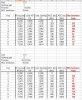
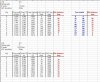
 :) ) and will post it later. Basically, it grabs the key ADC value from a LUT and then subtracts 2 and sets the "low range", then it adds 4 and sets the "high range", giving me -2 and +2 ( 4 number range) to compare against.

Button one, for example is dec 5 -- so my range would be 3-7... button two is dec 10 and would be 8-12, etc. I think that should take care of any noise issues.
 
Last edited:
Kyle-s4h said:
Page 114 of the datasheet (Figure 11-2) shows an analog input model -- Ric shows a resistor of 1K or less between the sampling switch and the input pin (I am not actually using it BETWEEN, I have it wired as a pull up)... and it also shows a 5pF cap between the input pin and Vss. That would work, and probably better. I have a 0.1 cap on the power rail near the ADC input, but not actually on it. The whole point to the resistor was simply to provide protection against a direct short on initialization -- the cap would do that. It would provide a constant power supply to the ADC input and protect against a direct short, no?
Reading this and looking at that picture I think you are wrong in the way that all that is on the right side of the ANx pin is INSIDE the PIC so don't worry about that, you have it.

Your application is on the left side of the ANx pin thus only VA and Rs in that picture.

The circuit represented in the dotted line is different for every design.
Yours is a 8k2 resisitor in serie with your key pad between +5V and GND. The connection between the 8k2 and the key pad is also connected to the PIC ADC pin preferably with an opamp with a gain of 2 in between :).
 
Ah! I understand you -- thanks!

I found out on my own that it doesn't work by creating a direct short! (It's not too bad with the Inchworm+ and Unicorn USB upgrade though... it simply creates an unknown USB device on any short... delete the device, do a reboot and you're good to go!) :)

I am going to do some reading on op amps later today and will probably go that route as it has been suggested by the pros! For now, I'm going to go stick a 1K in and see what changes -- if for nothing else than to understand what the different resistor values do to the ADC.

I have learned SO MUCH this morning -- thank you to all who have replied!
 
Kyle-s4h said:
Basically, it grabs the key ADC value from a LUT and then subtracts 2 and sets the "low range", then it adds 4 and sets the "high range", giving me -2 and +2 ( 4 number range) to compare against.

I'm a lazy guy and all these calculation is too much "work" for me or the PIC. :p

I would just use the ADRESH result as an index to a lookup table which give me "5" for ADRESH=4,5 or 6.

I think a +1 margin each side of the intended value is adequate and sufficient but certainly there is no harm going for a +2 margin.
 
Hmmm... never thought of it that way -- but unless I am not quite understanding what you are saying, my LUT would be huge. Using the posted values above, I would need 66 indices as my largest number is 65 ,plus one on the high side.

Compounding that would be the fact that I just went down to a 1K resistor, which provides bigger steps, but also a bigger range (0 - 226). This would mean I would need 227 indices?
 
OK, I've started by swapping out the 22K resistor with a 1K and here are the results, for those of you interested in the difference.

Steps are much greater now, but they also span a greater range.

#0 0x00 .00
#1 0x58 .88
#2 0x7E .126
#3 0x97 .151
#4 0xAB .171
#5 0xBB .187
#6 0xC7 .199
#7 0xD2 .210
#8 0xDA .218
#9 0xE2 .226

eblc1388 said:
I think a +1 margin each side of the intended value is adequate and sufficient but certainly there is no harm going for a +2 margin.

Thanks -- that was one of my original questions regarding ADC accuracy! :)

The keypad appears to work very well at this point. I have take out the 'debounce' routine as all it appears to do is add a noticable delay to keypresses. I do not appear to have any problems getting the read that I need to operate the correct button -- and I have yet to implement the range on either side of my known (I will though, to be on the safe side -- and yeah, I don't think 2 numbers either side will hurt, if you can afford them). Keypresses are very quick and responsive at this point -- back to testing! :)
 
1k series resistor ok fine for me :)
Find the expected ADC value for each key in the attached file.

Interesting is the fact that between keys 8 and 9 you have a variation of only 31 bits !!

With the 8k2 and opamp gain 2 setup the minimum difference between two keys is 91 bits !!
Less chance of error while decoding the keys :)

Your choice of course... ...
 

Attachments

  • Calcualtions.jpg
    Calcualtions.jpg
    91.8 KB · Views: 257
Thank you for the data -- it's a little overwhelming at the moment! :)

I am not saying that I will stick with the 1K... it's just what I have in available parts right now and can't leave the shop to go get more. ;) I will be reading up on op amps tonight and making purchases later or tomorrow, time depending.

I trust and appreciate what you all have to say, so if you say an op amp is the way to go, then I will go in that direction and learn about op amps. :D

I'm just doing the 1K tests just for that reason -- experimentation! :D
 
Your measured data match my calculations :D:D at least when I take the left aligned PIC stuff into account.
Since you don't use the 2 lower bits it's just like if you have only an 8 bit ADC instead of a 10 bit.
Columns E / J (dec) and F / I (hex) are equal.

Keep up the good work.

About OpAmps there is a design tool available at the TI site that calculates all the resistors for you :)
I try to find it back and post it later on ... ...
 

Attachments

  • Calculations-02.jpg
    Calculations-02.jpg
    123.6 KB · Views: 238
Kyle-s4h said:
I trust and appreciate what you all have to say, so if you say an op amp is the way to go, then I will go in that direction and learn about op amps. :D
Kyle-s4h, with the 1 k ohm resistor the equivalent resistance at the ADC input is well within the limits! I would concentrate on the software now. By the way, you're getting nice values :)

Be aware that general purpose op amps are not suitable for this task.


EDIT: have you mentioned which language you're using? A high-level language like C would make the task of mapping the keypad very easy!
 
Last edited:
Found it faster that I thought ...
**broken link removed**
Hit the "RESISTOR-CALC" link at the bottom to start.
 
Taking into consideration the new low impedance input circuit configuration, I wonder if an opamp is still required?
 
eng1 said:
By the way, you're getting nice values :)
Are you sure?
I wouldn't say that!
It's not the absolute value that matters, it's the minimum difference between two different keys.
With the 1k setup it's only 8 bits.
What are the specs of the PIC ADC, ADC value +/- 1bit or something like that? That brings the range even lower to only 6 bits!

eng1 said:
Be aware that general purpose op amps are not suitable for this task.
I think the two most important things for his application are:
Low power and single supply: a OPA2336 will do... ...
 
eblc1388 said:
Taking into consideration the new low impedance input circuit configuration, I wonder if an opamp is still required?
If it's not for the impedance thing then use it as a tool to get max difference between keys and use maximum ADC range.
See my calculations... ...
 
mcs51mc said:
It's not the absolute value that matters, it's the minimum difference between two different keys.
True.
I've re-checked the results more carefully :eek: I've seen the calculations you posted, good work ;)


mcs51mc said:
I think the two most important things for his application are:
Low power and single supply
I agree. I check availability too... I often had to pick another device in order to receive it quickly.
 
eng1 said:
EDIT: have you mentioned which language you're using? A high-level language like C would make the task of mapping the keypad very easy!

Assembler -- someday I'll learn C. :)


mcs51mc said:
If it's not for the impedance thing then use it as a tool to get max difference between keys and use maximum ADC range.
See my calculations... .

Although I agree with you, I wonder about the actual need for it. Not that I am trying to be cheap, just trying to think of the future -- of building a product thinking (wishfully) that you will sell a boat load of them -- and trying to keep the parts lists, especially if unneeded, to a minimum.

I do think your numbers using an op amp are much better than with a 1K setup, but will I ever see "drift" that will require having that many bits between results? I mean, that's why I went to an 8 bit resolution in the first place. I was actually happy with 5 bits! :) Simply because I am being generous by allowing 2 numbers on either side for a margin, thinking that it should only ever float by one either way.

Again, not trying to be cheap, if it's the better route to take, I'm all for it.
 
You have to think of noise, something no one can quantify.
You can of course take several ADC readings and average them.

By ignoring the least 2 bits you can only measure multiples of 4 bits.
4 bits on a 1024 bits range equals 0.0196V or
1 bit on a 255 bits range also equals 0.0196V
Noise of 19 mV will produce a +/-1 bit error in your readings.

Change your code in such way that you have automatic readings lets say every sec, write them down and see which variation you get.

Then move your circuit closer to any noise source and check ADC values again... ...


8 bit vs full 10 bit
I would use the full 10 bit range of the ADC, you have them for free, so why not using them? Code will be a little be larger but who cares (at least I don't need to write it :D)?


I'm absoluletly sure that the chance of an error in decoding will be much less with OpAmp and full 10 bit range, but I can't quantify it :( :eek:
 
Allow me to add these final considerations in my plea in the OpAmp / no OpAmp and 8 vs 10 bits case :)

What about the variation in resistor values over all produced key pads by LA Gard?
If they used standard 5% resistors you should also take that into account.

You provide us Ohmic data for the numeric keys.
What about the "*" and "#" keys, what are their Ohmic values?
And then, with no key pressed at all, what resistance do you measure.
With these three new values we maybe find even less difference between keys / no key!
So, please post those three values. Thanks for that.


OpAmp lecture: Here is one you definitely need to read since Single Supply is what you need :D
 

Attachments

  • TI_OpAmpCicuitCollectionSingleSupply.pdf
    163.1 KB · Views: 228
Last edited:
About the software, this is how I should do it, but since you're not me you can still do what you want :D:p:D

1) Use right aligned PIC data and the full 10 bits (range 0 to 1024)

2) Average successive 256 ADC readings to get 1 avgKeyValue. That is easily done by adding all ADC readings into one 24 bit variable and use only the upper 16 bits of the result. (256 readings of 1024 will result in 262144 = 040000; upper 16 bits are 0400 = 1024). I'm sure you can find math stuff on Nigel's site :)

3) Set the sampling rate of the PIC in such way that you get a avgKeyValue calculation every 0.1sec.

4) Compare succesive avgKeyValue to check if a key is pressed. If yes decode the new avgKeyValue using formula, look-up table, comparing... ... (correct choice can only be made once you know the final hardware = value for every key).

5) Wait for the "no key" code to seperate successive keys.
 
mcs51mc said:
Allow me to add these final considerations in my plea in the OpAmp / no OpAmp and 8 vs 10 bits case :)

What about the variation in resistor values over all produced key pads by LA Gard?
If they used standard 5% resistors you should also take that into account.

You provide us Ohmic data for the numeric keys.
What about the "*" and "#" keys, what are their Ohmic values?
And then, with no key pressed at all, what resistance do you measure.
With these three new values we maybe find even less difference between keys / no key!
So, please post those three values. Thanks for that.


OpAmp lecture: Here is one you definitely need to read since Single Supply is what you need :D

I'm not sure what the resistors are they use -- they are SMD, black with their Ohmic values printed on. Pretty generic looking to me! :)

The "*" and "#" keys are not used and not connected. They are, however, very easily usable by simply connecting a resistor to each one (LaGard designed them to be used, if need be, but has never used them).

When no button is pressed there is no connection (no resistance... but not 0 Ohm, that is button zero). If produces an ADC of FF.

Thanks for the pdf... will print it right now for my morning trip to the hot tub! :)
 
Status
Not open for further replies.

Latest threads

Back
Top